


4
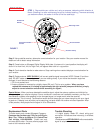
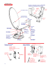
DIGITAL ELEVATION SENSOR ROOF CONNECTIONS
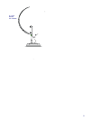
The illustrations below show the different methods of connecting wires at roof level. Method will depend on
model. Wire colors MUST MATCH, ie. red to red.
INSIDE RV
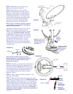
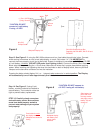
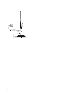
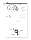
FIGURE 3D
Elevating
Shaft
Ceiling
Ceiling Plate/
Directional Dial
Measure
these
surfaces
after
pushing
Directional
Handle on
Elevating
Shaft
Directional
Handle
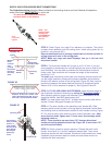
Cut elevating
shaft at inside
surface of
crank handle
housing; shaft
goes through
hex-shaped
opening by
screw.
Elevating shaft
Crank Handle
FIGURE 3F
FIGURE 3E
There should be no more than 1/32"
between directional handle and
ceiling plate/directional dial. If more
than 1/32", recut directional handle.
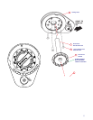
STEP 8. Check Figure 4 on page 5 for reference to numbers. The circled
numbers show assembly from the ceiling down. Install ceiling plate (#1) to
headliner, using screws (#2 ).
Be sure rotate/lock lever is pointing toward back of vehicle and hole in
ceiling aligns with hole in the ceiling plate.
NOTE: Make sure large and small keyways line up in the hub and
directional handle!
STEP 9. The directional handle will fit roofs up to 5-1/4" thick. If you are
using wedges to compensate for roof/ceiling slope, be sure to allow for this
extra thickness. You may add an extension to the directional handle for
thicker roofs. Each extension will increase the length of the directional
handle by 2-1/4".
To install, push directional handle (#4) over elevating shaft and push until
you feel slight resistance. Measure the distance between the directional
handle to the bottom surface of the ceiling plate, Figure 3D. Next, remove
handle and measure that same distance from end of directional handle.
Reduce 3/16" of this measure for proper fit. See Figures 3D and 3E
STEP 10. IF YOU ARE USING AN EXTENSION, adjust the total length of
the directional handle and extension by cutting the directional handle.
After adjusting parts for proper roof thickness, glue the extension to the
directional handle. Use ABS (plastic pipe) glue.
NOTE: For roofs thicker that 6-9/16", a longer aluminum hex shaft will be
needed. Contact Winegard Company for this part.
STEP 11. Flip down handle on the elevating crank handle (#5). Slide
elevating crank handle up shaft until snug against directional handle. Mark
the elevating shaft at inside bottom surface of crank handle housing, Figure
3F. Cut shaft at mark, after removing crank handle. Reinstall crank. After
screw touches shaft, tighten only 1/4 turn more. Screw simply holds
elevating crank on.
NOTE: There should be no more than 1/32" between directional
handle and ceiling plate/directional dial, Figure 3D. If more than 1/32",
recut directional handle.
STEP 12. Check system for proper operation. Elevate dish with crank
handle. A minimum of 14 turns is needed to elevate dish. Then, move
directional handle with dish elevated. Directional handle should turn freely.
If possible, have someone watch to make sure coax does not bind or
interfere with dish movement.
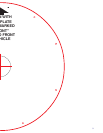
This wire harness connects to the digital
elevation sensor on the antenna.
NOTE: This
terminal is NOT
weatherproof
and CANNOT be
left outside on
the roof.
Snap
connectors
together