


6
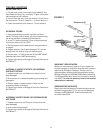
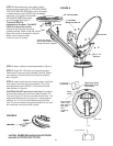
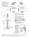
STEP 3. Remove backing from gasket. Attach
adhesive side to base plate. IF YOU ARE USING
THE ROOF WEDGE (RW-5000), use 3/16” gasket
included with the mount UNDER the roof wedge.
Install the 1/16” gasket included with
RW-5000 BETWEEN the mount
and roof wedge.See Figure 7.
The word FRONT is
embossed on the base. This MUST
FACE the front of the vehicle.
Secure to roof using two mounting
screws provided. Check inside the vehicle.
Be sure the shaft is centered in the hole.
Attach crank handle to shaft.
Crank unit up until it stops.
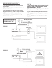
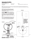
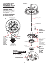
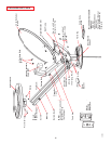
STEP 4. Attach reflector to backup assembly, Figure 6.
STEP 5. Attach RS-1000 antenna to elevating tubes.
Use the two E-clips and pins provided, Figure 6. Attach
coax cable to F-jack on antenna and slide on weather
boot, Figure 6.
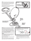
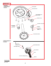
STEP 6. Install remaining mount base screws. Install the
vent tube on the back of the mount base. (This is the
side opposite the word FRONT.) The hole for the vent
tube is shown in Figure 8.
CAUTION: DO NOT seal hole in vent tube. Put sealant
around the outside of the vent tube, approximately 1/2”
from end, Figure 8. Push the vent tube into the hole. The
sealant will seal the hole as you push in. Leave approxi-
mately 2 to 2-1/2” of the vent tube extending from the
hole. Put a small amount of approved sealant on the roof
and under the vent tube to hold in place.
Attach RS-1000 to
ELEVATING TUBES using
E-Clips and Pins supplied.
PINS
E-CLIPS
RS-1000 ANTENNA
REFLECTOR
(4) ANTENNA
MOUNTING BOLTS
(4) 1/4 - 20
HEX NUT
FIGURE 6
FIGURE 8
FIGURE 7
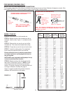
Cable-entry plate
Minimum 3” from
mount base
Cable
clamp
Do not attach
cable clamp
with screw to
base plate
until
installing
cable.
Base plate
6-1/8”
Travel Bracket