


8
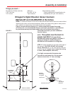
STEP 15. The directional handle and threaded rod
will fit roofs up to 5-1/4” thick. If you are using
wedges to compensate for roof/cceiling slope, be
sure to allow for this extra thickness. You may add
an extension to the directional handle for thicker
roofs. Each extension will increase the length of the
directional handle by 2-1/4”. Figure 11
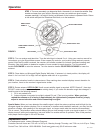
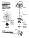
STEP 16. Press the directional handle onto the hub.
Point arrow on the directional handle towards the ro-
tate/lock lever to orient to the splines.
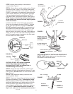
STEP 17. Install the washer and nut on the threaded
rod. Tighten the nut enough to snug the directional
handle to the hub.
STEP 18. IF YOU ARE USING AN EXTENSION, ad-
just the total length of the directional handle and
extension by cutting the directional handle.
After adjusting parts for proper roof thickness, glue the
extension to the directional handle. Use ABS (plastic
pipe) glue.
NOTE: For roofs over 5¼” thick, a longer aluminum
hex shaft is needed. Contact Winegard for this part.
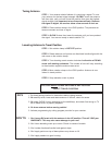
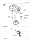
FIGURE 11
WITH ROOF WEDGE
Measure from top of
roof wedge to ceiling.
WITHOUT ROOF WEDGE
Measure from top of
roof to ceiling.
TOP OF ROOF
WEDGE
CEILING
TOP OF ROOF
CEILING
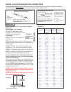
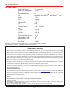
FIGURE 12
Plastic
Plug
Spacer
Spring
Worm
Gear
Ceiling
Plate
Directional
Handle
Threaded
Rod
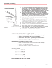
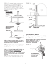
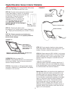
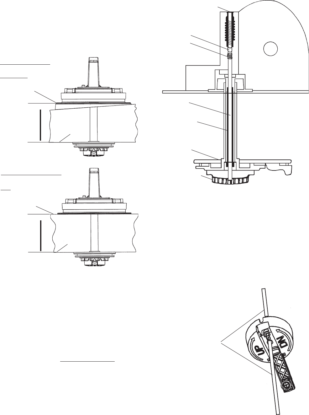
CUTTING SHAFT LENGTH
Flip down handle on the elevating crank handle. Slide
elevating crank handle up shaft until snug against the
directional handle.
Mark the elevating shaft at the inside bottom surface
of crank handle housing, Figure 13.
After removing crank handle, cut
shaft at mark. Reinstall crank.
Elevating Shaft
Cut Elevating Shaft at
inside surface of crank
handle housing; shaft goes
through hex-shaped
opening by screw.
FIGURE 13