


4
WARNING
DO NOT INSTALL COUPLERS, SPLITTERS, ETC.
BETWEEN THE POWER SUPPLY AND THE AN-
TENNA. INSTALLATION OF ANY ITEM ON THE DOWN-
LEAD MAY CAUSE A SHORT IN THE SYSTEM. THE
DOWNLEAD SUPPLIES +12 VDC TO THE PREAMP IN
THE ANTENNA.
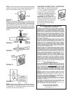
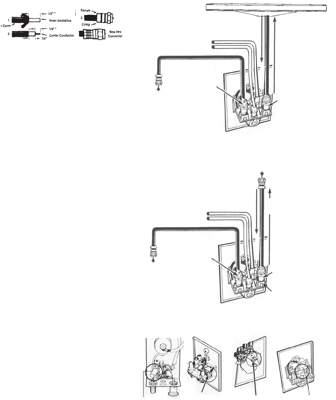
HOW YOUR SYSTEM WORKS
Turning power supply on sends +12 VDC up cable to
antenna. Voltage energizes transistors on amplifier in
antenna head. TV signal comes back down cable to
outlets.
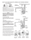
TO TEST SYTEM
1. Make sure TV set is working properly.
2. Switch power supply ON and OFF to see if there is a
difference in the picture quality while watching TV. If
there is NO difference, proceed to the next step.
CAUTION
The power supply should be turned OFF when con-
necting/disconnecting cables to power supply and
antenna, but should be turned ON when testing for
voltage.
3. Disconnect cable from antenna and check for +12
VDC at test point #1. If there is +12 VDC, the power
supply is OK and the antenna needs to be replaced.
4. If there is no +12 VDC at test point #1 reconnect the
cable to antenna. Remove power supply from wall and
visually inspect for burnt/broken parts. If there are any
broken or burnt parts replace power supply.
5. Disconnect cable from antenna jack on power supply.
Check for +12 VDC at test point #2. If there is +12 VDC
then there is a problem in the cable connecting the
power supply to the antenna. Repair/ replace cable.
6. If +12 VDC is not present at test point #2, check that
the red indicator is ON. If not, check the polarity of the red/
white wires and check the +12 VDC source. If there is still
no +12 VDC replace the power supply.
HOW YOUR
SYSTEM WORKS
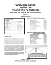
WHAT TO DO WHEN YOUR RV/TV ANTENNA IS NOT WORKING PROPERLY
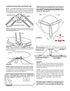
INSTALLING COAX CABLE ON
FC- 5910 CONNECTORS
STEP 1: Strip outer cover back 1/2"* from end of cable. Fray braid back
as far as outer cover will allow.
STEP 2: Trim braid close to outer cover and remove 1/4"* of inner insulation
being careful not to nick center conductor. Make sure no foil or braid can
touch center conductor.
STEP 3: Slide connector tip between braid and inner insulation (braid and
foil, on foil shield cable) and push connector on cable as far as it will go.
Crimp built-in ferrule with appropriate crimping tool. Do Not crush cable
out-of-round. *If installing in very hot weather, increase these dimensions
1/8".
* If installing in very hot weather, increase these dimensions 1/8".
RF CHOKE RF CHOKE POLYSWITCH POLYSWITCH
AMPLIFIED
TV SIGNAL
+12VDC
ANTENNA
CONNECTION
SET 2
2ND SET
HOOK UP
WHITE
RED
HOOKS INTO +12VDC BATTERY +
GND -
TO TEST SYSTEM
TEST POINT #1
+12VDC AT ANTENNA
REMOVE CABLE
FROM ANTENNA
WHITE
RED
+ 12VDC
GND
ANTENNA
CONNECTION
TEST POINT #2
+12VDC AT
ANT. JACK
2ND SET
NO +12VDC
AT THIS POINT
SET 2
AT SET 2 JACK
FIGURE 1 FIGURE 2 FIGURE 3 FIGURE 4
POWER SUPPLY
IN METAL HOUSING
POWER SUPPLY
NO POLYSWITCH
POWER SUPPLY
W/POLYSWITCH
POWER SUPPLY
W/POLYSWITCH
+ Point center wire
- Point outside of
connector