IR Receivers
1
INSTALLATION INSTRUCTIONS
172-78
XTRA LINK
®
2
REMOTE CONTROL EXTENSION SYSTEM
The Xtra Link 2 system provides full remote control operation of a satellite receiver, cable box or VCR from
a second room by sharing the coaxial cable connecting your video equipment to this second room’s TV.
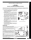
The 172-78 Xtra Link consists of the following supplied parts:
1. One 291-10 Infrared Receiver. It is placed at the
remote room location to receive IR signals from the
handheld remote controller.
2. One INJ77 Injector. This unit, located in the Remote
Room, injects the remote control signal into the room-
to-room coaxial cable (along with the TV signal) and
passes it to the CPL77 Coupler in the Main room. It
also provides quick connection of the 291-00 IR Re-
ceiver and 781C-78 Power Supply cables.
3. One CPL77 Coupler. Located in the Main Room, this
Coupler extracts the remote control signal from the
coaxial cable and passes it to the emitters that control
your source equipment. In addition, the CPL77 con-
tains a 2-way RF splitter so that the TV signal can be
fed to a local TV.
4. One 284M Dual IR Emitter. The emitters on this
device allow control of two infrared remote controlled
audio/video components.
5. One 781C-78 Power Supply. This plugs into an
unswitched 220-240 VAC outlet to provide power to
the 291-00 IR Receiver.
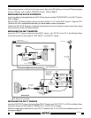
CONNECTIONS
The Xtra Link system uses the coaxial cable that
carries the TV RF signal from the source equip-
ment in the main room to the remote room, to
send the IR control signals back to the source
equipment. The coaxial cable may be up to one
mile in length.
If you already have a coaxial cable connecting
your video equipment with a remote room, your
current hookup should be similar to Fig. 1. If it
isn't, run a single length of RG59 or preferably
RG6 cable from the Main Room to the Remote
Room.
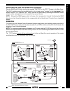
NOTE: If RF amplifier(s) are used anywhere in
the line of coaxial cable between the CPL77
Coupler and the INJ77 Injector, you must use a
Xantech BYPASS77 KIT to route the IR com-
mands around the amplifier(s).
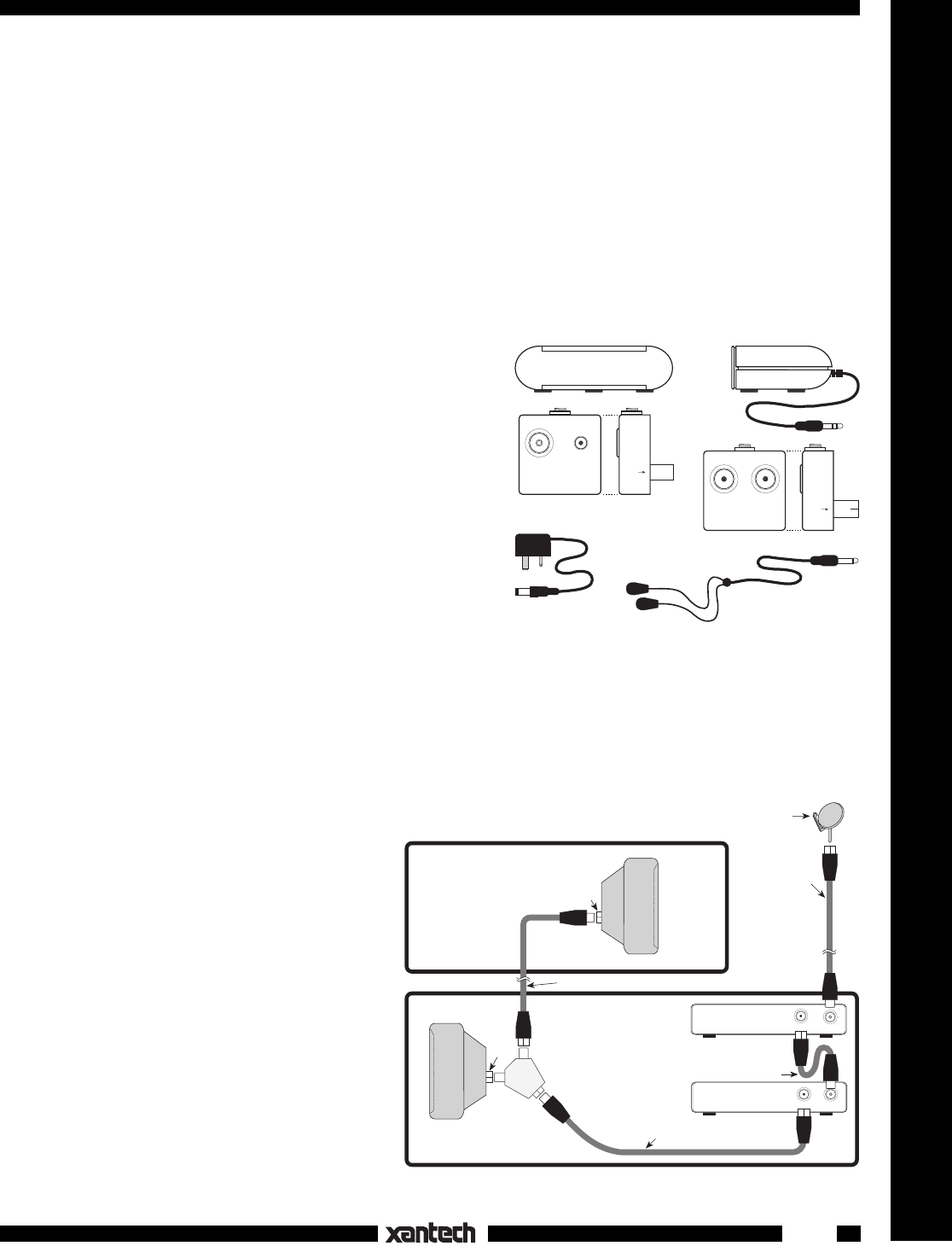
781C-78
Power Supply
284M
Dual Mouse Emitter
Front View Side View
IR RECEIVER
INJ77 INJECTOR
ANT INPUT
+12 V
REMOTE TV
EMITTER
LOCAL TV
CPL77 COUPLER
SAT/VCR
TO TV
SIDE VIEW
291-00 IR Receiver
SIDE VIEW
172-78 Xtra Link 2 System Parts
Fig. 1 Basic System Without Xtra Link
Satellite Dish
REMOTE ROOM
RF IN
MAIN ROOM
Room-to-Room Coaxial Cable
RF INOUT TO TV
SATELLITE RECEIVER
(Back Panel)
RF IN
VCR
(Back Panel)
OUT TO TV
Coaxial Cable
1ST
TV
RF SPLITTER
2-Way
Coaxial Cable
Coaxial Cable
2ND
TV
RF IN