


2
172-78
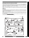
When using more than one Xtra Link for more rooms, be sure the RF splitters you use are DC passing types,
such as Xantech part number 04027500 (2-way). Refer to Fig. 3.
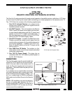
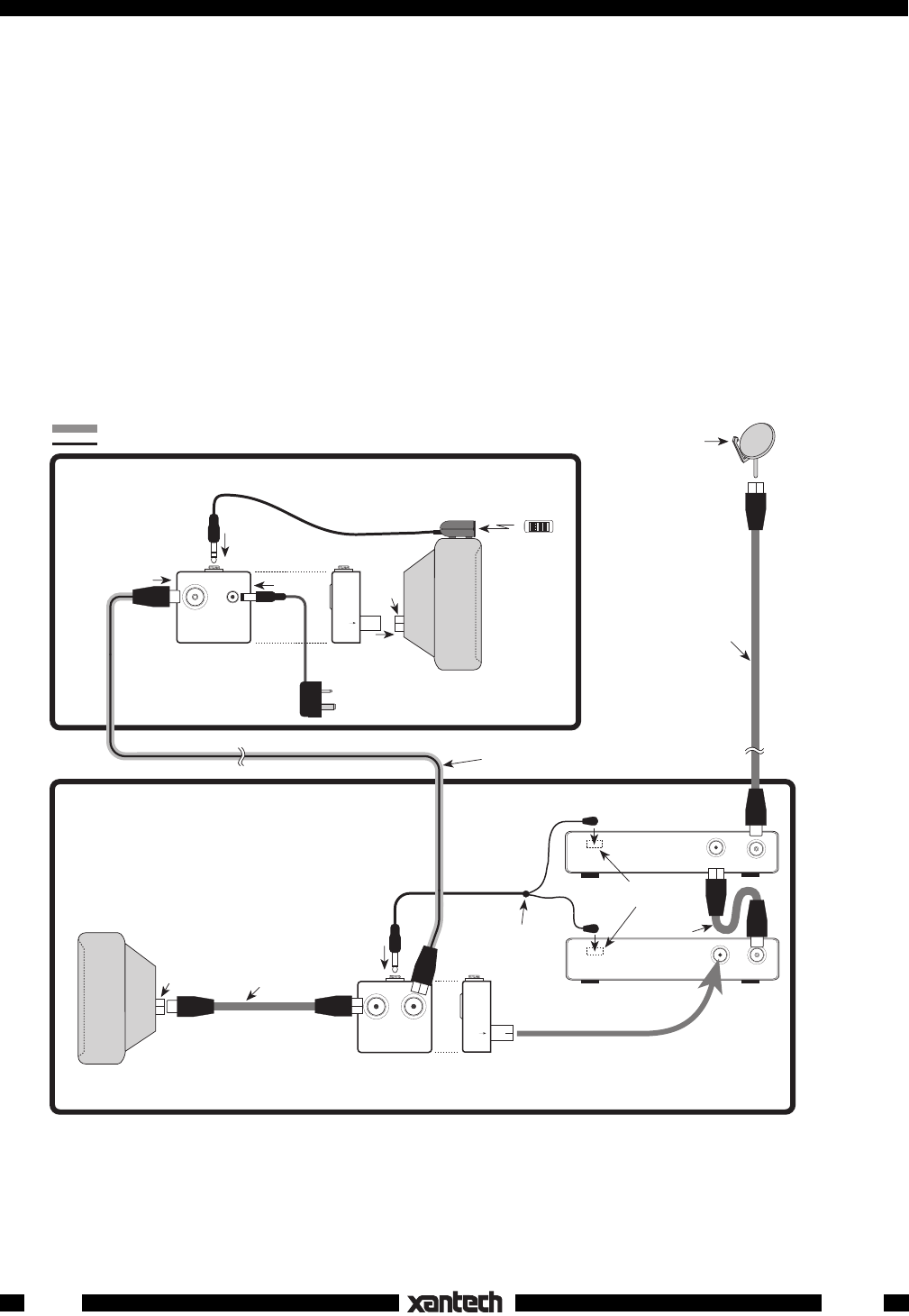
INSTALLING THE 291-00 IR RECEIVER
Insert the cable mini plug attached to the 291-00 into the jack marked "IR RECEIVER" on the INJ77 Injector.
Refer to Fig. 2.
Plug the 781C-78 Power Supply cord into the jack marked "+12 V" on the INJ77 Injector. Plug the 781C-
78 into a 220 VAC unswitched outlet after you have made all other connections.
Position the 291-00 IR Receiver so that the infrared beam from the handheld remote control has a direct
view to the front of the unit (within 20 feet).
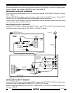
INSTALLING THE INJ77 INJECTOR
Insert the "TO TV" plug on the back of the INJ77 Injector into "RF IN" on the TV in the Remote Room.
Connect the room-to-room cable to "ANT INPUT" on the INJ77 Injector.
Satellite Dish
TV SIGNAL PATH
IR REMOTE CONTROL PATH
Hand Held
Remote
REMOTE
ROOM
RF IN
284M
Dual Mouse
Emitter Assembly
(Included)
MAIN ROOM
CPL77 COUPLER
(included)
Room-to-Room Coaxial Cable
(not included)
Coaxial Cable
(Not included)
Place emitters on
the IR sensor
window on front
panel of each
controlled unit.
Emitter
RF INOUT TO TV
SATELLITE
RECEIVER
(Back Panel)
RF IN
VCR
(Back Panel)
Emitter
IR Sensor Windows
(Front Panel)
Coaxial Cable
(not included)
To 220 V AC
(unswitched)
INJ77 INJECTOR
(included)
291-00
IR RECEIVER
(included)
2ND
TV
781C-78
Power Supply (included)
1ST
TV
RF IN
Coaxial Cable
(not included)
REMOTE
TV
EMITTER
LOCAL TV
CPL77 COUPLER
SAT/VCR
Front View Side View
OUT TO TV
IR RECEIVER
INJ77 INJECTOR
ANT INPUT
+12 V
TO TV
Front View
Side View
Fig. 2 Basic Xtra Link Hookup
INSTALLING THE CPL77 COUPLER
Insert the "SAT/VCR" plug on the back of the CPL77 Coupler into "OUT TO TV" on VCR in the Main Room.
Connect the room-to-room cable to "REMOTE/TV" on the CPL77 Coupler.
Make the remaining connections from the CPL77 Coupler to the TV, the VCR to the satellite receiver, etc.,
as shown in Fig. 2.