IR Receivers
1
172-94X
XTRA LINK 2
®
REMOTE CONTROL EXPANSION KIT
The Model 172-94X is an expansion kit intended for use when installing Xtra Link 2's in more that one room.
It includes only the parts needed for each additional room, thus avoiding the unnecessary duplication of
couplers, emitters and coax jumper cables.
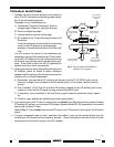
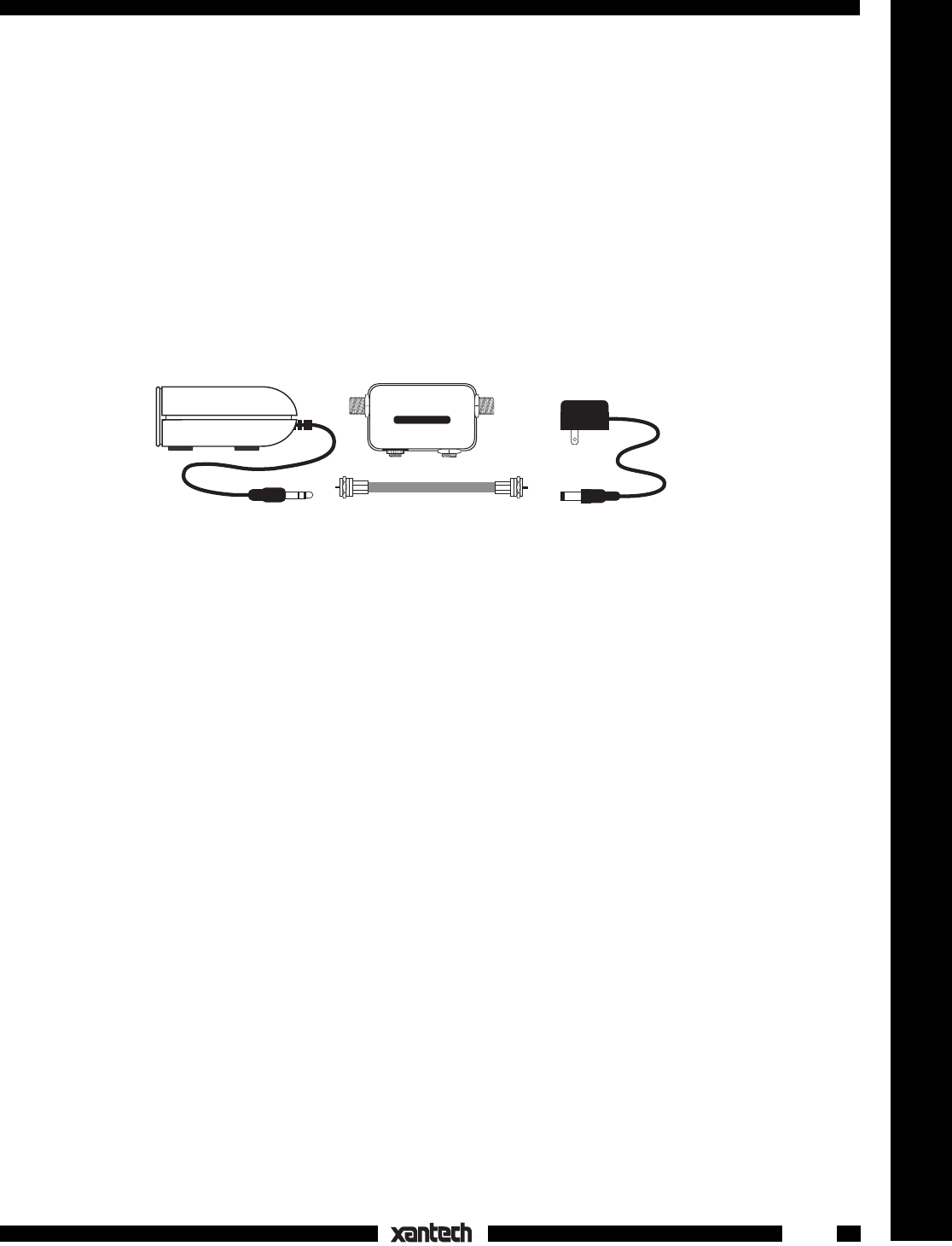
The 172-94X kit consists of the following supplied parts:
1. One 291-10 Infrared (IR) Receiver. It is placed at the remote room location to receive IR signals
-from the handheld remote controller.
2. One INJ94 Injector. This unit, located in the Remote Room, injects the remote control signal into the
room-to-room coaxial cable (along with the TV signal) and passes it to the CPL94B Coupler in the
Main room. It also allows quick connection of the 291-00 IR Receiver and 781RG Power Supply
cables.
3. One short coaxial cable. Connects the INJ94 Injector to the TV in the Remote Room.
4. A 781C-00 Power supply. This plugs into an unswitched 120V AC outlet to provide power to the
291-00 IR Receiver.
INSTALLATION
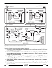
Fig. 2 shows the connections necessary when using a 172-94X expansion kit to provide remote control from
an additional room.
Begin by installing a standard 172-94 kit, for one of the remote rooms. (Refer to the owner's manual for the
Xtra Link 2 Model 172-94, for basic system connections). Next, using one of the 172-94X kits, install it into
the second remote room, making connections as shown in Fig. 2. Note that a 2-way RF splitter is used to
split the coax signal to each of the remote rooms. This splitter
must be
a DC passing type, such as the
Xantech Model 200-00.
NOTE: If RF amplifier(s) are used anywhere in the line of coaxial cable between the CPL94B Coupler and
the INJ94 Injectors, you
must use
a Xantech BYPASS94 KIT to route the IR commands around such
amplifier(s).
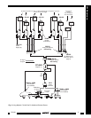
ADVANCED MULTIROOM HOOKUP
Fig. 3 shows an advanced system using six 172-94 plus five 172-94X Expansion Kits, in a multiroom
installation. The connection concept is essentially the same as in Fig. 2, except for the additional splitters,
RF amplifiers, etc. that need to be taken into consideration.
INJ94
Injector
291-00
IR Receiver
Coax Jumper Cable
781C-00
Power Supply
INJ94 INJECTOR
TV
INPUT
IR
RCVR
+12 V
Fig. 1 172-94X Kit Parts
INSTALLATION INSTRUCTIONS