


● The fan is operated by a remote
switch.
The fan indicator light shows when it
is switched on.
● An integral timer provides an
adjustable overrun period after the
fan is switched off.
Condensation operation
● The fan operates automatically if the
relative humidity is above the set
level.
● The integral timer provides an
adjustable overrun period after the
relative humidity level has fallen.
Switched operation
● A manual operation remote switch
starts the fan. The fan indicator light
shows when it is switched on.
● The integral timer provides an
adjustable overrun period after the
fan has been switched off.
Condensation operation
● The fan operates automatically at low
speed if the relative humidity rises
above the set level.
● The integral timer provides an
adjustable overrun period after the
fan has been switched off.
Boost operation
● The integral pull cord switches the fan
on to run at high speed. The fan
indicator light shows when high
speed has been selected.
● A remote switch may be used as an
alternative to the pull cord. If this is
used, cut off the pull cord, after
ensuring that the pull cord switch is in
the “off” position.
● This fan is operated by a remote
switch.
● This fan is operated by a remote
switch.
Before making any adjustments,
isolate the fan completely from the
mains electricity supply.
Adjusting the timer overrun
The overrun timer is factory preset at
approximately 20 minutes. The time is
adjustable between approximately
2 to 20 minutes.
1. Remove the back draught shutter/
grille assembly (see “Mounting the
fan in the hole” section).
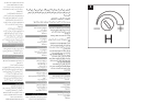
2. Turn the adjuster marked “T” anti-
clockwise to reduce the timer overrun
(see Fig.H).
3.
Turn the adjuster clockwise to increase
the timer overrun (see Fig.H).
4. Replace the back draught shutter/
grille assembly (see “Mounting the
fan in the hole” section).
Adjusting the humidistat setting
The internal humidity sensor is factory
set at approximately 70%. The level is
adjustable between approximately
50% and 90% relative humidity.
Remove the back draught shutter/grille
assembly (see “Mounting the fan in the
hole” section).
Turn the adjuster marked “H” anti-
clockwise to decrease the relative
humidity level of the room (see Fig. 1).
Turn the adjuster clockwise to increase
the relative humidity level of the room
(see Fig.l).
Replace the back draught shutter/grille
assembly (see “Mounting the fan in the
hole” section).
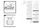
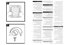
Trickle ventilation is equivalent to that
provided by an airbrick or similar device.
1. Remove the back draught shutter/
grille assembly (see “Mounting the
fan in the hole” section).
2. HOLD THE SHUTTER VANES FULLY
OPEN.
3. Push down firmly on the trickle vent
catch until it clicks into position then
release the shutter vanes. (See
Fig.F item 6).
4. Pull the trickle vent catch towards you
until it clicks into position.
5. Refit the back draught shutter/grille
assembly, see “Mounting the fan in
the hole” section, ensuring that the
actuator lever is in the “fully down”
position.
A QUALIFIED ELECTRICIAN MUST
CARRY OUT ALL CLEANING.
NOTE: THE FAN WILL CONTINUE TO
OPERATE WITH THE INNER GRILLE
REMOVED HENCE IT MUST BE
ISOLATED COMPLETELY FROM THE
MAINS BEFORE ANY WORK IS
CARRIED OUT.
1. Before cleaning, isolate the fan
completely from the mains
electricity supply. Allow 3 minutes
for the impeller to stop rotating
and the powered shutter to close.
(Cleaning on the GXC6 and GXS6
can begin once the impeller has
stopped rotating).
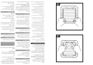
2. Remove the back draught shutter/
grille assembly by pressing the
release catch located on the side of
the unit with a 6mm screwdriver or
coin, whilst pulling the grille forward.
To remove the back draught shutter,
lay face down and pull shutter
forwards see Fig.G1 and Fig.G2.
3. To remove the impeller. Unscrew the
central screw and remove it together
with the washer. Place screw and
washer to one side.
4. To clean the impeller, either wipe it
with a damp, lint free cloth or wash it
in warm soapy water. Thoroughly
dry the impeller and refit.
Replace the screw and washer
ensuring that they are securely fitted.
5. Clean the back draught shutter/grille
assembly and impeller in warm soapy
water.
Do not use strong detergents
or chemical cleaners.
6. Thoroughly dry the back draught
shutter/grille assembly and refit by
sliding the grille back over the realise
catches, the catches will locate in and
secure the grille (see Fig.G3 and
Fig.G4). For GXS6 MODEL: Ensure
that the actuator lever is in the “fully
down” position.
7. Do not immerse the fan in water or
other liquids to clean any other
parts of the fan.
Never use strong solvents to clean
the fan.
Apart from cleaning, no other
maintenance is required.
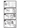
1. Back draught shutter.
2. Fan assembly.
3. Outer grille
4. Ladder strips.
5. Terminal cover
6. Trickle vent catch
7. Rear cable entry.
8. Top cable entry.
9. Rating plate.
10. Lugs for screw mounting.
11. Grille.
12. Screw hole caps.
13. Actuator lever (GXS6 model only).
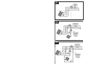
GX6T / GXC6T / GX6HT and
GX6HT2 only
GX6T
GX6HT2
To allow trickle ventilation
Trickle ventilation
To fully close the shutters and
stop any back draught
GX6HT
GXS6
GX6 (IP25)
Maintenance
Components Fig. D