


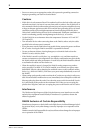
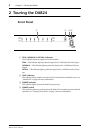

Rear Panel
3
DA824—Owner’s Manual
Rear Panel
A
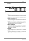
COM port
This port is for updating the DA824’s internal firmware and is not used in normal oper-
ation.
B
WORD CLOCK THRU connector
This BNC connector transmits the wordclock signal received at the WORD CLOCK IN.
C
WORD CLOCK 75
Ω
ON/OFF switch
This switch is used to terminate the wordclock signal received at the WORD CLOCK
IN. See “Wordclocks” on page 8 for more information.
D
WORD CLOCK IN connector
This BNC connector is used to connect an external wordclock source. Normally, the
DA824 locks to a wordclock signal derived from the SLOT digital audio inputs, but
when a usable wordclock signal is present at the WORD CLOCK IN connector, this is
used instead. See “Wordclocks” on page 8 for more information.
E
OUTPUT (BAL) connectors
These male XLR-3-32 type connectors and 1/4" phone jack (TRS) connectors are the
analog outputs for each channel. Both types of connector are electronically balanced.
XLR connectors are wired as follows: pin-1 ground, pin-2 hot (+), and pin-3 cold (–).
When using both the XLR and phone jack output of a channel at the same time, ensure
that the total load is greater than 600
Ω
.
F
Power cable
This power cable is used to connect the DA824 to an AC outlet. See “Connecting the
Power Cord” on page 1 for more information.
G
SLOT
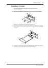
This slot is for use with optional mini YGDAI cards, which offer various digital input
options. See “Digital I/O Cards” on page 4 for more information.
SLOT
COM
THRU
75Ω IN
OFF
ON
WORD CLOCK
DA CONVERTER
MODEL DA824
8 2314567
8 2314567
OUTPUT
(BAL)
1 52 4
76
3