ATLAS 830 P/N 1200780L1 (AC)/1200781L1 (DC)
For more detailed documentation, visit us online at www.adtran.com
Quick Start Guide
Quick Start Guide, 61200780L1-13A, August 2002 Technical Support 1-888-4ADTRAN (1-888-423-8726) Copyright 2002 ADTRAN, All Rights Reserved
SEE MANUAL BEFORE
REMOVING POWER SUPPLY
OFF
ON
CAUTION: FOR CONTINUED PROTECTION
AGAINST RISK OF FIRE, REPLACE
ONLY WITH SAME TYPE AND RATING
OF FUSE.
12A/125V
+
-
48 VDC, 6A
USE COPPER
CONDUCTORS ONLY
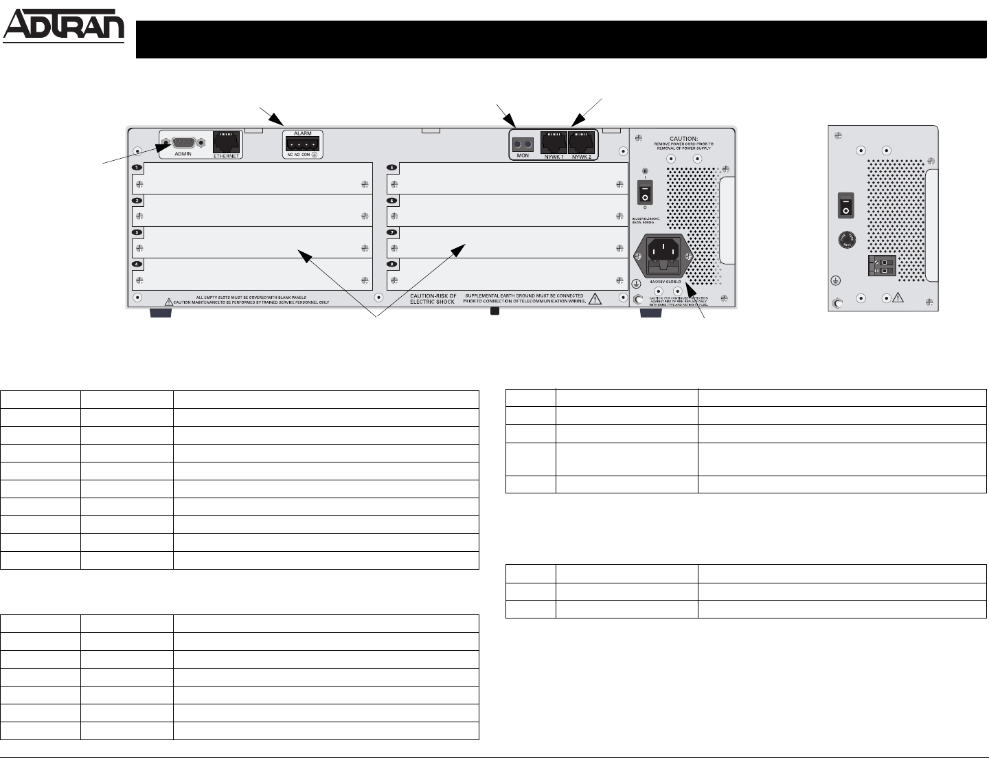
Network T1/PRI Ports
Optional DC
Power Supply
P/N 1200229L1
T1/PRI Monitor Jacks
Alarm Relay Connection
Admin Interface
Option Module Slots
Power Supply Slot
Reviewing the Rear Panel Design
Admin Pinout
10/100BaseT Ethernet Pinout
PIN NAME DESCRIPTION
1 DCD Data Carrier Detect (output)
2 RD Receive Data (output)
3 TD Transmit Data (input)
4 DTR Data Terminal Ready (input)
5 SG Signal Ground
6 DSR Data Set Ready (output) -- not connected
7 RTS Request to Send (input)
8 CTS Clear to Send (output)
9 RI Ring Indicate (output) -- not connected
PIN NAME DESCRIPTION
1 TX1 Transmit Positive
2 TX2 Transmit Negative
3 RX1 Receive Positive
4,5 — Unused
6 RX2 Receive Negative
7, 8 — Unused
Alarm Relay Connection Pinout
DC Power Supply Connection
(Optional P/N 1200229L1)
PIN NAME DESCRIPTION
1 Normaly Closed (NC) Opens when a selected alarm condition is present.
2 Normally Open (NO) Closes when a selected alarm condition is present.
3 Common (COM) Common connection between external circuitry
and NC or NO terminal.
4 Chassis Ground (GND)
PIN NAME DESCRIPTION
1 + Ground (GND)
2--48VDC


