724-746-5500 | blackbox.com
724-746-5500 | blackbox.com
Page 9
Chapter 3: Installing the Heat-Transfer Door
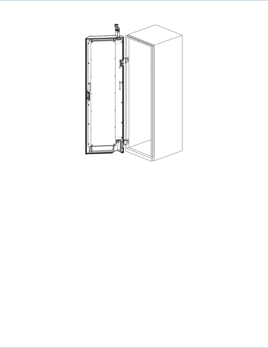
Figure 3-2. Top-feed model.
3.1 Main Tasks
Installing the Heat-Transfer Door consists of the following main tasks:
1. Remove the existing IT enclosure’s rear door, hinges, and door latch (if installed).
2. Attach the Transition Frame (if required) as described in the Transition Frame Installation Guide supplied with each Transition
Frame.
3. Attach the Heat-Transfer Door hinges directly to the IT enclosure rear frame or to the Transition Frame (if required).
4. Place the Heat-Transfer Door assembly on both hinges.
5. Connect the supply and return hoses from the chilled water source, the Coolant Management System (CMS), or External
Manifold to the couplings on the Heat-Transfer Door.
6. Fill the Heat-Transfer Door with treated water and purge remaining air from the coil.
7. Secure the hoses and the Heat-Transfer Door assembly.
NOTE: Connecting the hoses from a CMS unit to the Heat-Transfer Door creates the required secondary loop in the water-
circulation system. See the Cold Front Heat-Transfer Door Planning Guide for information about primary and secondary
loops in the water-circulation system.
3.2 Required Components and Tools
1. Heat-Transfer Door assembly
2. Heat-Transfer Door hinge kit (ships with the Heat-Transfer Door [HTD])
3. Heat-Transfer Door documentation package (ships with the HTD)
4. Transition Frame Kit (if required, ships with the HTD)


