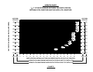
ANT WIND VEL. DIM “d” CONC VOL. DIM “d” CONC VOL. GROUND POLE
80 MPH 9” 1.5 FT
3
7” 1.2 FT
3
90 MPH 11” 2.2 FT
3
7” 1.2 FT
3
Mo. 611652931
.90M 100 MPH 13” 3.0 FT
3
8” 1.5 FT
3
110 MPH 15” 4.0 FT
3
10” 2.4 FT
3
SEE NOTE 1
125 MPH 18” 5.8 FT
3
12” 3.5 FT
3
80 MPH 10” 1.8 FT
3
7” 1.2 FT
3
Mo. 611652931
1.0M 90 MPH 13” 3.0 FT
3
8” 1.5 FT
3
100 MPH 15” 4.0 FT
3
9” 1.9 FT
3
SEE NOTE 2
108 MPH 16” 4.6 FT
3
10” 2.4 FT
3
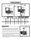
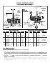
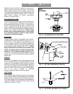
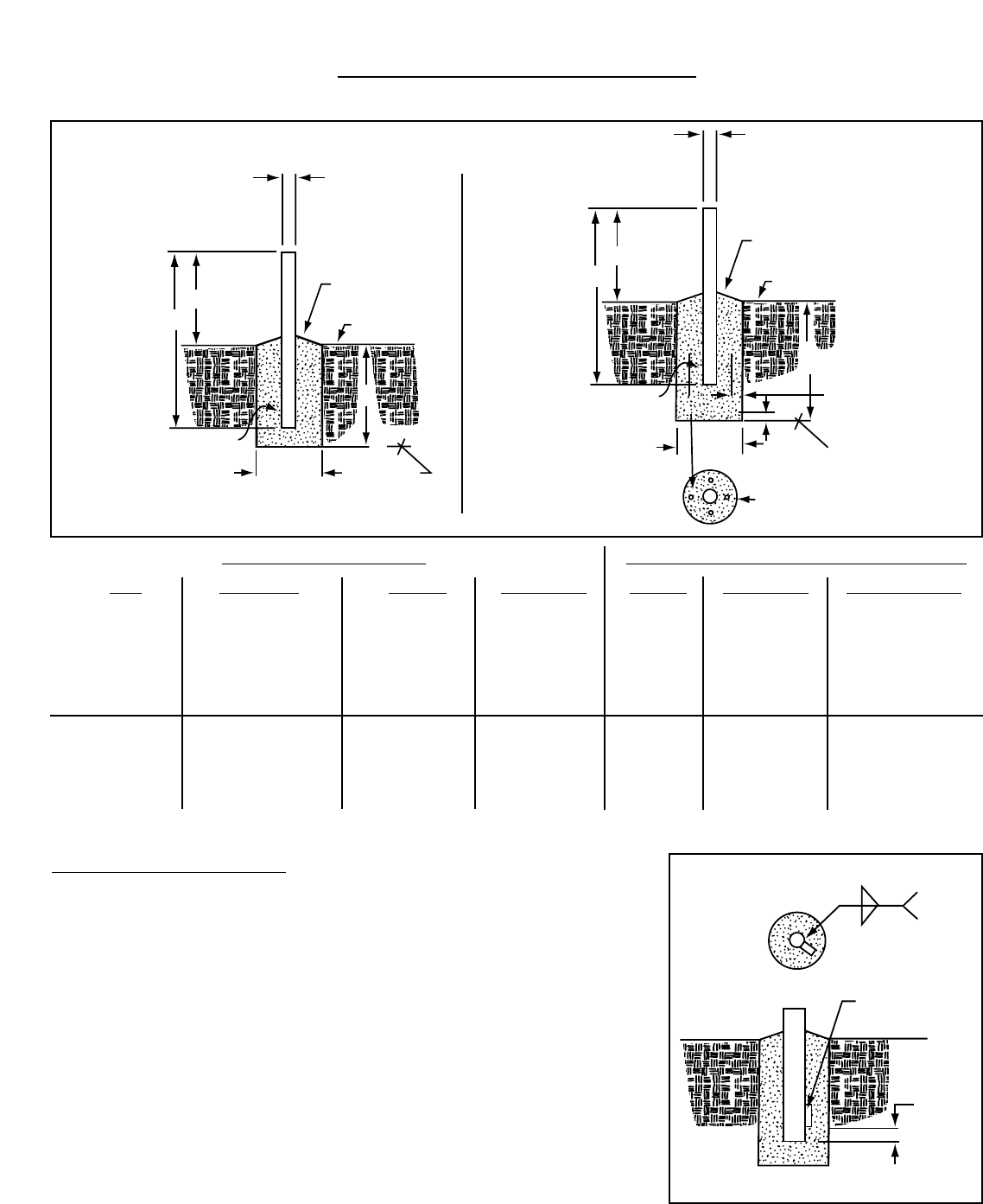
PIER FOUNDATIONS DEEP FROST LINE FOUNDATIONS
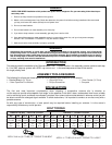
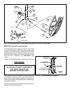
POLE SPECIFICATIONS:
2” SCH 40 2³⁄₈” O.D. x .154 Wall x 72” Long Steel - CM PN 611652931 w/Oval End and
Powder Paint Finish.
1. When wind velocity exceeds 108 MPH on the .90m antenna at heights shown, the
ground pole must be a heavy wall pipe as follows: 2” pipe (2³⁄₈” O.D.) Schedule 80
(.218”
wall thickness) and purchased locally.Field weld ¹⁄₄ x 1¹⁄₂ x 5 key as shown in
Fig. 1.0
to prevent rotation in the concrete or use 3” O.D. ground pole and AZ/EL cap.
2. These charted values based on using Model 611652931 ground pole, 2.375 O.D. x
1.54 wall.When wind velocity exceeds 108 MPH, use 3” O.D. ground pole and AZ/EL
cap.
3. Pole and foundation design based on the following criteria: (a) Uniform Building Code
Exposure C and 1.5 stability factor, (b) Vertical soil pressure of 2000 pounds per square
foot, (c) Lateral soil pressure of 400 pounds per square foot, (d) Concrete compres-
sive strength of 2500 pounds per square inc h in 28 days.
4. CAUTION - The foundation design shown does not represent an appropriate design
for any specific locality since soil conditions vary and may not meet design criteria given
in Note 1.You should consult a local professional engineer to determine your soil con-
ditions and appropriate foundation.