2-9
SW8/12 VGA Ars • Installation and Operation
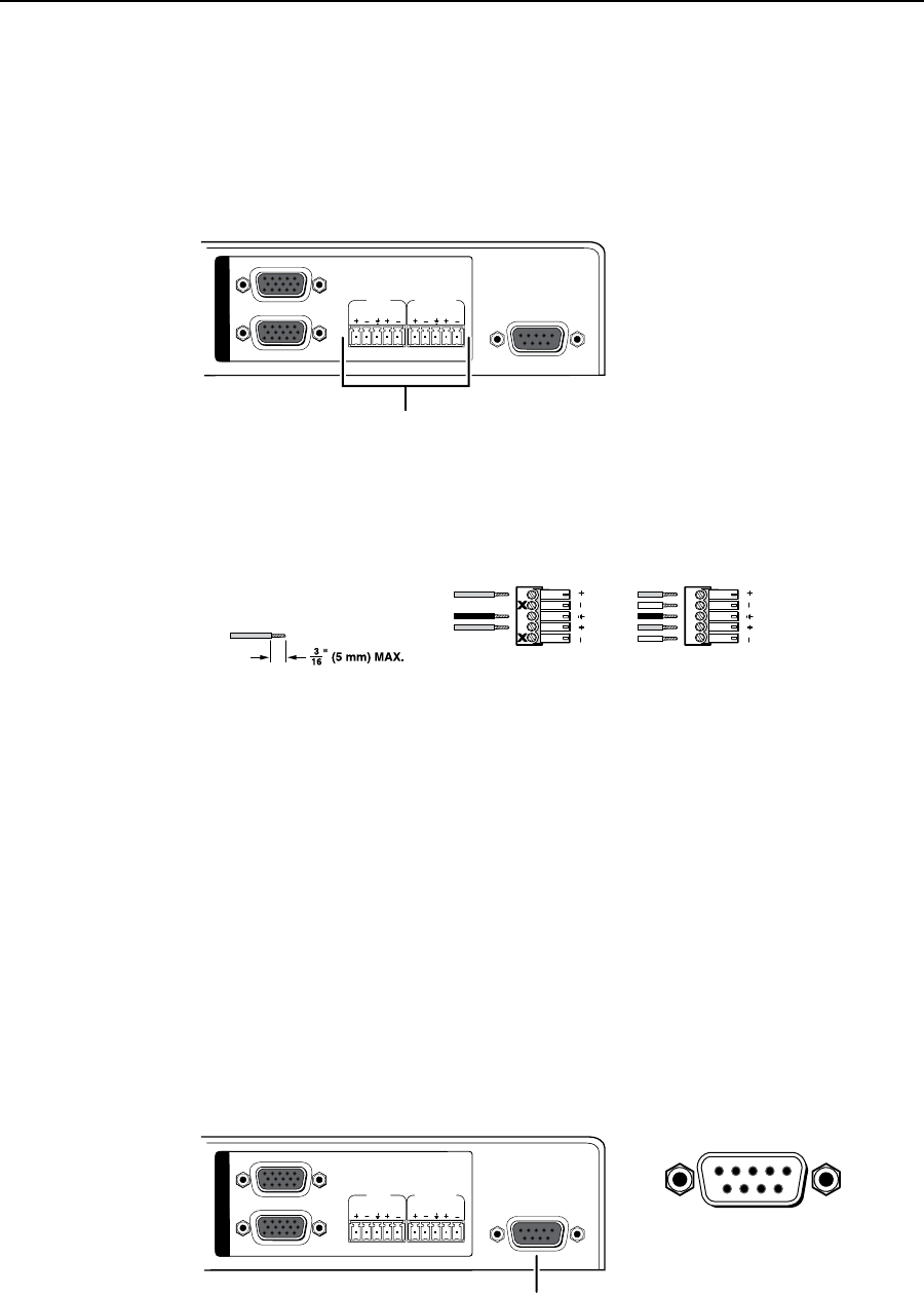
Audio output connections
Theswitcherhavetwo3.5mm5-polecaptivescrewaudiooutputports.
TheFixedportdeliversaxedvolume,stereobalanced/unbalancedaudiooutput.
The Variable port delivers a variable volume, stereo balanced/unbalanced audio
output.Thevolumerangeis0(-84dB)through100(0dB).Thedefaultvolume
settingis100(0dB).VolumeiscontrollableonlyviatheRS-232port.
RS-232
SW12 VGA Ars
1
2
FIXEDVARIABLE
LRLR
O
U
T
P
U
T
S
Audio output ports
Figure 2-10 — Audio output ports
Wire the captive screw connectors as shown below.
C
Connect the sleeve to ground (_). Connecting the sleeve to a
negative (-) terminal will damage the audio output circuits.
Do not tin the wires!
Unbalanced
Stereo Output
Tip
NO GROUND HERE.
Sleeve(s)
Tip
NO GROUND HERE.
Balanced
Stereo Output
Tip
Ring
Tip
Ring
Figure 2-11 — Captive screw connectors
N
A balanced audio output provides a +6 dB gain. An unbalanced audio output
provides a 0 dB gain.
Remote control connection
AnRS-232serialcontrolportattherightedgeoftherearpanelisusedforcomputer
orinfrared(IR)remotecontrolofthedevice.Theswitcher’srmwarecanbe
upgradedthroughtheRS-232port.Seechapter3,“OperationandControl”.
TheRS-232portcommunicationsprotocolsare:9600baud,8databits,1stopbit,
no parity, and no flow control.
IRremotecontrolrequiresuseoftheIR102RemoteControlKit(part#70-224-01)
Forcomputerorinfraredremotecontrol,onlypins2(transmitdata),3(receive
data),and5(ground)arerequired.Disconnectallotherconductorsinthe
attachment cable for proper operation.
RS-232
SW12 VGA Ars
1
2
FIXED VARIABLE
LRLR
O
U
T
P
U
T
S
RS-232 control port
DB9 Pin Locations
Female
51
96
Figure 2-12 — RS-232 control port


