- 11 -
LGE Internal Use OnlyCopyright © LG Electronics. Inc. All rights reserved.
Only for training and service purposes
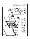
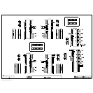
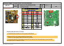
4. Total Assembly line process
4.1. Adjustment Preparation
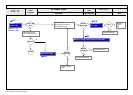
▪ W/B Equipment condition
CA210
: CCFL/EEFL -> CH9, Test signal: Inner pattern(80IRE)
LED -> CH14, Test signal: Inner pattern(80IRE)
▪ Above 5 minutes H/run in the inner pattern. ("power on" key
of Adjustment remote control)(Only EEFL)
* White Balance table.
▪ Edge LED module change color coordinate because of
aging time
▪ Apply under the color coordinate table, for compensated
aging time
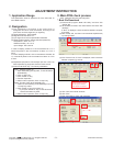
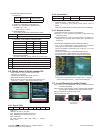
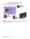
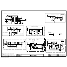
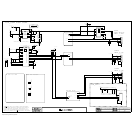
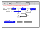
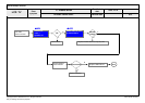
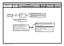
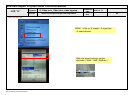
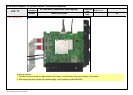
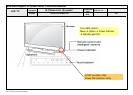
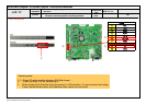
* Connecting picture of the measuring instrument
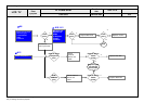
(On Automatic control)
Inside PATTERN is used when W/B is controlled. Connect to
auto controller or push Adjustment R/C POWER ON -> Enter
the mode of White-Balance, the pattern will come out.
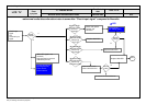
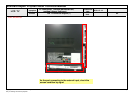
* Auto-control interface and directions
(1) Adjust in the place where the influx of light like floodlight
around is blocked. (Illumination is less than 10 lux).
(2) Adhere closely the Color analyzer(CA210) to the module
less than 10 cm distance, keep it with the surface of the
Module and Color analyzer's prove vertically.(80° ~ 100°).
(3) Aging time
- After aging start, keep the power on (no suspension of
power supply) and heat-run over 5 minutes.
- Using 'no signal' or 'POWER ONLY' or the others, check
the back light on.
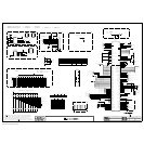
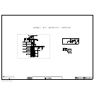
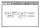
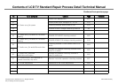
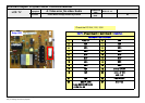
▪ Auto adjustment Map(RS-232C)
RS-232C COMMAND
[CMD ID DATA]
Wb 00 00 White Balance Start
Wb 00 ff White Balance End
<Caution>
Color Temperature : COOL, Medium, Warm.
One of R Gain/G Gain/ B Gain should be kept on 0xC0, and
adjust other two lower than C0.(When R/G/B Gain are all
C0, it is the FULL Dynamic Range of Module)
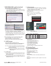
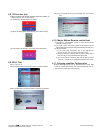
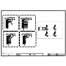
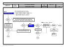
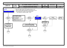
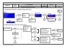
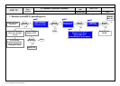
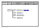
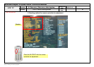
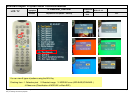
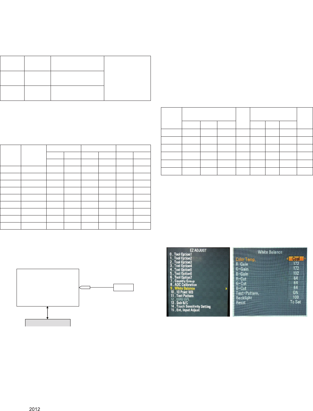
* Manual W/B process using adjust Remote control.
▪ After enter Service Mode by pushing "ADJ" key,
▪ Enter White Balance by pushing "
►
" key at "9. White
Balance".
* After you finished all adjustments, Press "In-start" key and
compare Tool option and Area option value with its BOM, if
it is correctly same then unplug the AC cable. If it is not
same, then correct it same with BOM and unplug AC cable.
For correct it to the model's module from factory Jig model.
* Push the “IN STOP" key after completing the function
inspection. And Mechanical Power Switch must be set
“ON”.
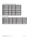
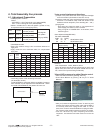
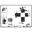
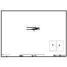
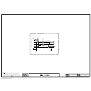
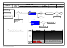
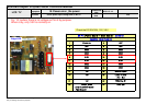
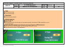
Full White Pattern
CA-210
COLOR
ANALYZER
TYPE : CA-210
RS-232C Communication
Cool 13,000 K
X=0.269 (±0.002)
Y=0.273 (±0.002)
<Test Signal>
Inner pattern
(204gray, 80IRE)
Medium 9,300 K
X=0.285 (±0.002)
Y=0.293 (±0.002)
Warm 6,500 K
X=0.313 (±0.002)
Y=0.329 (±0.002)
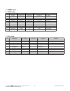
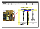
GP4
Aging
time
(Min)
Cool Medium Warm
X y x y x y
269 273 285 293 313 329
1 0-2 280 287 296 307 320 337
2 3-5 279 285 295 305 319 335
3 6-9 277 284 293 304 317 334
4 10-19 276 283 292 303 316 333
5 20-35 274 280 290 300 314 330
6 36-49 272 277 288 297 312 327
7 50-79 271 275 287 295 311 325
8 80-119 270 274 286 294 310 324
9 Over 120 269 273 285 293 309 323
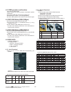
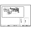
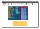
RS-232C COMMAND
[CMD ID DATA]
MIN
CENTER
(DEFAULT)
MAX
Cool Mid Warm Cool Mid Warm
R Gain jg Ja jd 00 172 192 192 192
G Gain jh Jb je 00 172 192 192 192
B Gain ji Jc jf 00 192 192 172 192
R Cut 64 64 64 128
G Cut 64 64 64 128
B Cut 64 64 64 128