Rockwell Automation Publication 1734-UM001E-EN-P - July 2013
4 About the Modules
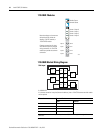
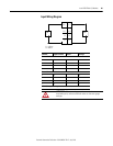
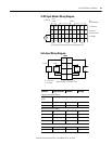
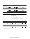
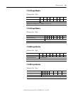
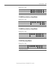
– Channel 1 Status (1 byte)
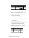
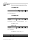
• Output modules consume 4 bytes of data.
– Channel 0 Data (2 bytes)
– Channel 1 Data (2 bytes)
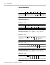
• Output modules produce 2 bytes of data.
– Channel 0 Status (1 byte)
– Channel 1 Status (1 byte)
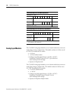
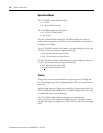
• Operational modes
– Current - two modes
• 0 to 20 mA
• 4 to 20 mA (default mode)
– Voltag e - t wo mo des
• 0 to 10V (default mode)
• -10 to +10V
• Individually set channel mode
• Scaling - conversion to engineering units
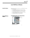
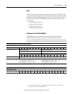
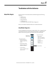
Input Modules
These features are available on input modules.
• Latching alarms, when set, latch low- and high-alarm status information.
Available alarms include:
– Low.
– Low Low.
– High.
– High High.
• Disable alarms - disables all channel alarms and faults so they are not
reported in the channel status field. Four different alarms are available.
• Settable update rate update rate determines how often an input channel is
scanned.
• Notch filter is selectable for both inputs (50, 60, 250, and
500 Hz).
• Digital filter sets a time constant.
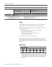
Output Modules
These are features available on output modules.
• Latching alarms, when set, latch low and high clamp alarm status
information.