36
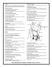
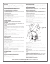
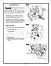
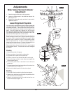
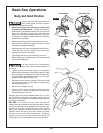
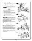
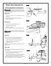
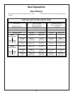
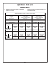
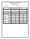
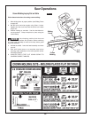
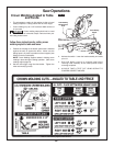
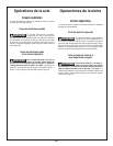
Blade 45° To The Table
1. Rotate table 1 to 0° position and lock in place.
2. Move sliding fence to its proper position. (See Sliding
F
ence on page 50.)
3. Lower head assembly. Lock in place.
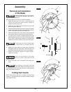
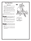
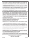
4. Loosen bevel lock handle
4 and tilt the head assembly to
45° bevel. Check the 45° bevel stop. The bevel indicator
should be on the 45° mark, the 45° bevel stop should be
in full contact with the 45° bevel stop screw, and the blade
2 should contact the full length of the combination square
3 (Figure 8).
5. If the blade is not 45° with the table, adjust 45° bevel stop.
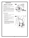
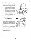
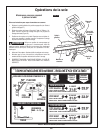
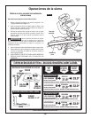
45° Blade Alignment
a. Move sliding fence to proper position. (See Sliding
Fence on page 50.)
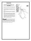
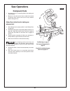
b. Loosen bevel lock handle
4 (Figure 9).
c. Bevel the head assembly to 0° to access the
adjustment screw
5.
d. Using the small hex wrench located behind the
sliding fence, adjust the screw
5 up or down.
e. Move the head assembly back to 45° and re-check
with combination square.
f. Repeat if necessary.
g. Check that bevel indicator is pointing to the 45° mark
on the bevel scale (see Figure 8). If bevel indicator is
not aligned with the 45° mark, first recheck the blade
squareness to the table and 0° bevel indicator
alignment. Then, repeat the 45° blade alignment and
make appropriate adjustments.
Adjustments
FIG. 8
FIG. 9
13
5
4
2