Page 6 | DEFENDER™ Vogelzang International Corp. TR001B | 20110118.4
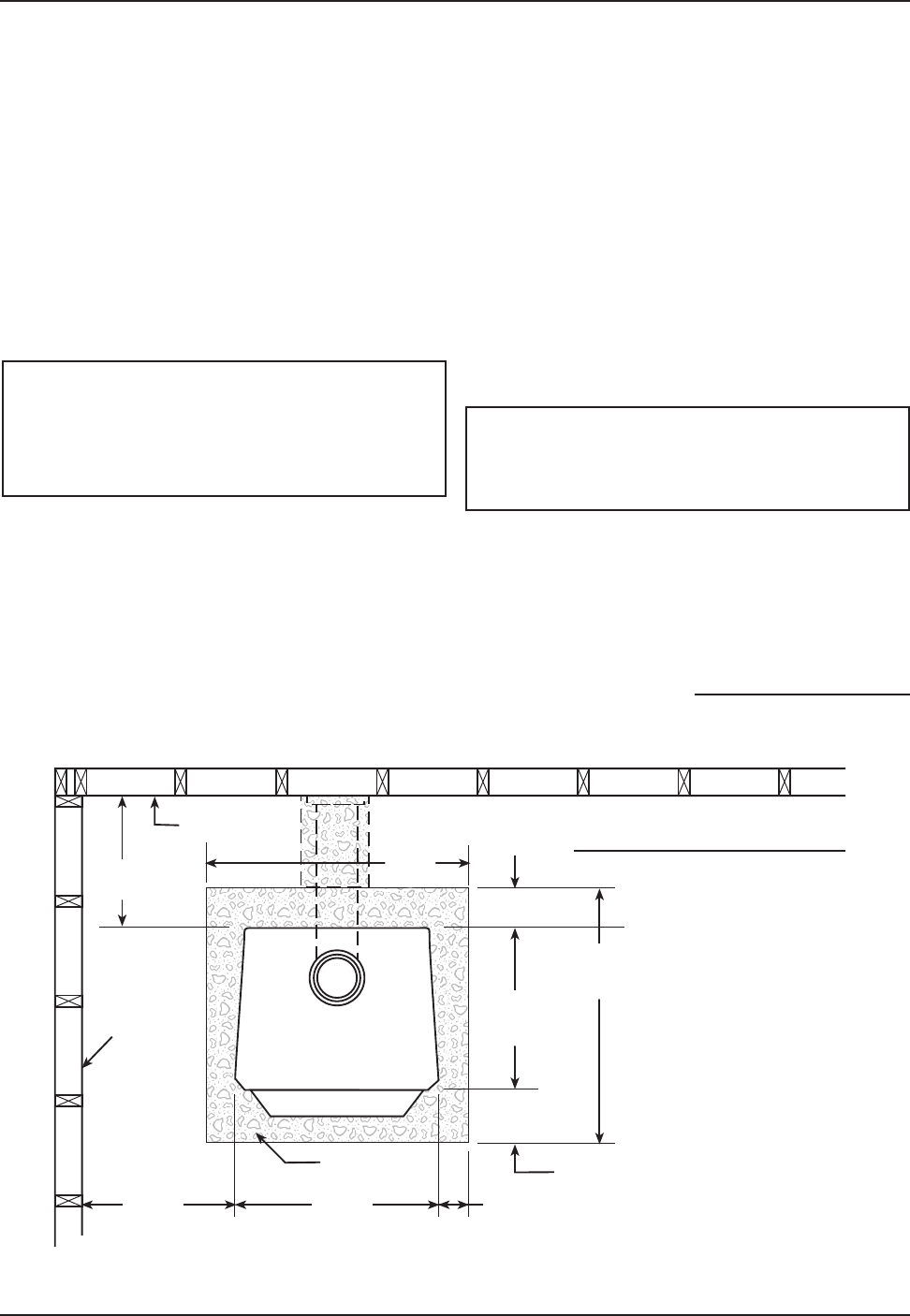
Fig. 5 – Top View Minimum Clearance Dimensions from Combustible Surfaces
FLOOR
PROTECTOR
DASHED LINES SHOW HORIZONTAL CHIMNEY CONNECTOR
AND ADDITIONAL FLOOR PROTECTOR REQUIRED BENEATH
AND EXTENDING 2” BEYOND EACH SIDE
COMBUSTIBLE CONSTRUCTION IN ACCORDANCE WITH NFPA 211
BACKWALL
SIDEWALL
12"min.
18"
46"
16"min.
6"min.23"
15"
min.
12"min
TOP VIEW
35"
TR001B
1. The stove must be placed on solid concrete, solid
masonry, or when installed on a combustible floor,
on a listed floor protector, such as Hy-C or Impe-
rial Model UL 3648BK or equivalent. Floor protec-
tor must be 1/2” minimum thickness (“k” value =
0.84, R value = 0.59, see page 21 for calculation
formulas) non-combustible material or equivalent.
The base must extend at least 16” beyond the front
of the access door, 6” to the sides of fuel opening,
12” behind the stove and must extend under and
2 inches beyond either side of the stove pipe if it
is elbowed towards a wall. (See figures 5 & 7 and
consult local building codes and fire protection
ordinances).
.
CAUTION: (FIRE HAZARD) CARPETING AND
OTHER COMBUSTIBLE MATERIAL SHALL
NOT COVER THE FLOOR PROTECTOR. THESE
MATERIALS MUST REMAIN OUTSIDE OF
COMBUSTIBLE CLEARANCES, SEE FIG. 5 – 7.
.
2. The stove must have its own flue. Do not con-
nect this unit to a chimney flue serving other
appliances.
3. After observing the clearances to combus-
tible materials (figures 5–7), locate your floor
protector accordingly (figure 5) and careful-
ly place the stove in your selected location.
LOCATING STOVE
continued on next page
Install stove pipe, elbows, and thimble as
required, utilizing either a recently cleaned and
inspected 6” masonry chimney or a 6” i.d. listed
chimney.
4. Use round 6” dia., minimum 24 MSG black or 26
MSG blue steel stove pipe to connect the stove to
the chimney. Do not use galvanized stove pipe. Se-
cure pipe sections with three (3) sheet metal screws
in each stove pipe and/or elbow joint to firmly hold
the pipe sections together. Do Not connect this
stove to any air distribution or duct system.
5. R ec h ec k c l ea r an c es f ro m th e st ov e,
connector stove pipe, and corner clearanc-
es using the illustrations in figures 5–7 and
your local building codes or fire protection
ordinances.
NOTICE: Any wall containing combustible
materials such as wooden studs, drywall and
faced with brick or stone must be considered
a combustible surface.
6. Do Not install this stove in a mobile home,
Manufactured Home, trailer or Tent – NO
EXCEPTIONS! (HUD Federal Standard: 24 CFR
7. The c lea rances provi ded are min imum
dimensions determined by Omni Test Lab-
oratories, Inc., the manufacturer’s testing


