Page 12 / TR009 PERFORMER™ VGZ-029 / 20110519.0
CHIMNEY CONNECTIONS continued …
Consult your insurance company if you cannot find a
qualified expert.
CAUTION: NOT ALL FIREPLACES ARE SUIT-
ABLE FOR CONVERSION TO A WOOD STOVE.
CHECK WITH A QUALIFIED EXPERT.
Many prefabricated fireplaces are of the “zero-
clearance fireplace” category. These consist of multi
layered metal construction. They are designed with
enough insulation and/or air cooling on the base, back
and sides so they can be safely installed in direct con-
tact with combustible floors and walls. Although many
prefabricated fireplaces carry endorsements from na-
tionally recognized organizations for use as fireplaces,
they have not been tested for connection to wood stove
heaters. Connecting a stove to such a device will void
the manufacturer’s warranty.
Steel-lined fireplaces are constructed with
1/4” firebox liner, an air chamber in connection with 8”
of masonry. These can be safely used with wood burn-
ing stoves. They contain all the essential components
of a fireplace, firebox, damper, throat, smoke shelf,
and smoke chamber. Many look identical to masonry
fireplaces and should be checked carefully before con-
necting a stove to them.
Venting a stove directly into a fireplace does not
meet code and should not be attempted. (This consti-
tutes connection to another appliance - the fireplace.)
Combustion products will be deposited and build up in
the firebox or fireplace. The stove warranty will be void
with such an installation. Do not create a hazard in your
home by connecting in this manner.
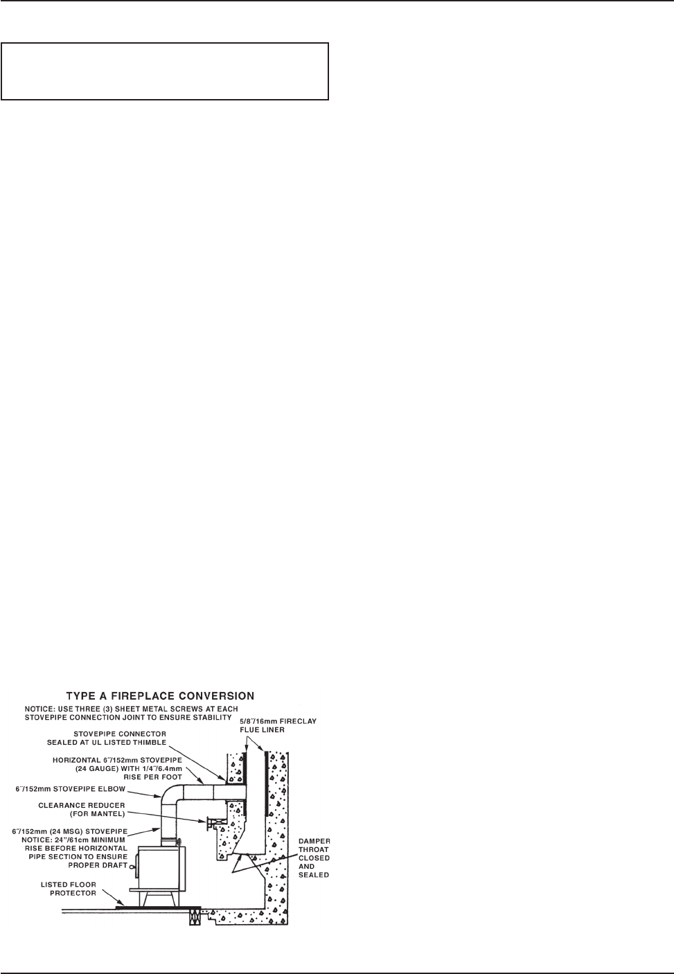
FIREPLACE INSTALLATION
NOTE: DO NOT ATTEMPT TO ROUTE THE CHIM-
NEY CONNECTOR PIPE THROUGH THE THROAT OF
THE FIREPLACE. Directly connecting the stovepipe
into the existing masonry chimney (figure 19 “Type A”
Figure 19 - Fireplace Conversion
fireplace conversion) of the fireplace is the ONLY ap-
proved method of installation. This is a complicated and
involved process and to ensure safety should only be
done by a qualified installer.
1. An entry hole must be cut through the masonry and
tile liner with minimal damage to the liner. At least 8”
of liner must remain below the entry position. When
locating the stove and stovepipe, all minimum clear-
ances must be observed from combustible surfaces
including mantels, combustible trim work, ceilings,
and walls. Positioning the center of the stove pipe
entry into the chimney 24” below the ceiling should
insure proper clearance for a 6” stovepipe.
2. Install a metal or fire clay (5/8” minimum thickness)
thimble. Make sure the thimble is flush with the inner
surface of the chimney liner and does not protrude
into the flue (see figure 14 on page 9).
3. Secure the thimble with refractory mortar. The
thimble should be surrounded by 8” of solid unit
masonry brickwork or 24” of stone.
4. Install the stovepipe into the thimble as far as pos-
sible without extending past the flue lining (see
figures 14 & 15 on pages 9 & 10).
5. A small airspace (about 1/2”) should remain
between the stovepipe and thimble to allow for
expansion of the pipe. Seal this airspace with high-
temperature caulking or ceramic wool.
6. Secure and seal the damper in the closed posi-
tion using high-temp caulking, ceramic wool, or
furnace cement. Also check to see if the chimney
has a clean out. If it does, make sure it is closed
and sealed as well. A leaky clean out will greatly
reduce draft efficiency.
If you have any questions regarding venting your
stove, contact the manufacturer or contact the National
Fire Protection Association (NFPA) and request a copy
of the latest editions of NFPA Standard 211 and NFPA
Standard 908. Their address is:
Battery March Park, Quincy, MA 02269.


