20 Freedom HF Installation Guide
Basic Installation Procedures
AC Output Connections for the Freedom HF 1055 EMS
and Freedom HF 1800 EMS Models
1. Ensure AC and DC power sources are turned off.
2. Install the required circuit breaker in the inverter distribution panel
receiving AC power from the inverter.
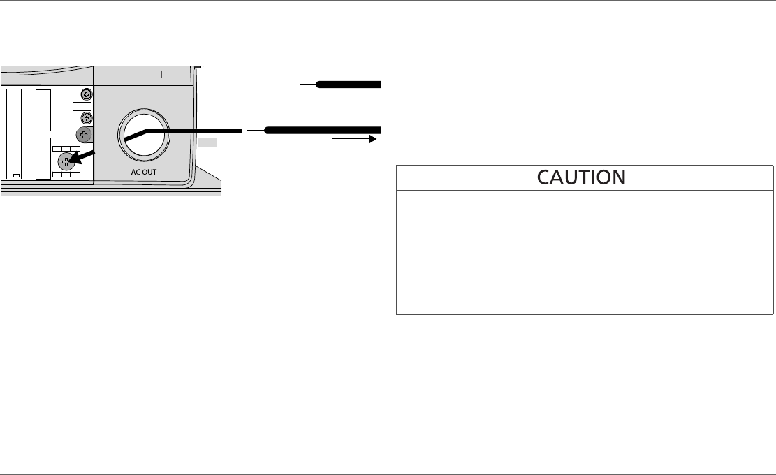
3. Remove the GFCI unit to expose the AC output terminals inside the
wiring compartment behind the AC OUT knockout.
4. Install a strain-relief clamp on the AC OUT knockout.
5. Strip a single strand (e.g. Romex) AC output wire, as appropriate.
6. Locate the Line, Ground and Neutral terminals on the AC output
terminal labeled as L, GND, and N respectively.
7. Passing the wire through the knockout, insert the Ground AC output
wire into the Ground terminal slot on the unit.
8. Repeat steps 5 to 7 for Line and Neutral connections.
Tighten the wire attachment screws to a torque of 1.3–1.8 lbf-ft (1.76–
2.44 Nm). Leave some wiring slack inside the wiring compartment.
Ensure you have maintained correct polarity and that there are no
loose strands of wire.
9. Secure the wires by adjusting the strain-relief clamp.
10. Install the GFCI back into the front panel of the unit.
11. Alternatively, if you do not reinstall the GFCI, make sure that you cap
the exposed wires and install a blanking plate to cover the space
vacated by the GFCI.
12. Connect the other end of the wires to a circuit breaker in the inverter
distribution panel.
FREEDOMHF 1800 EMS
AC OUTPUT
N
L GND
CAUTION! Do notconnect the ACOUT toany
other source of power .Damage to unit may occur .
to circuit
breaker
10mm
ground terminal
REVERSE POLARITY DAMAGE
Improper connections (connecting a line conductor to a neutral
conductor, for example) will cause the Freedom HF to malfunction and
may permanently damage the inverter. Damage caused by a reverse
polarity connection is not covered by your warranty.
Failure to follow these instructions can damage the unit and/or
damage other equipment.
Freedom HF Install Guide.book Page 20 Thursday, November 24, 2011 11:06 AM
