


56 78-8130-6150-0 Rev G
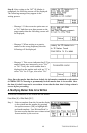
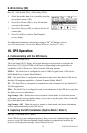
3. Connection Diagrams
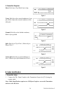
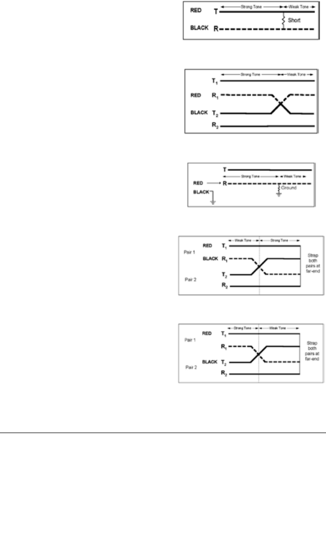
Short: Red clip to Tip; Black clip to ring.
Figure 1
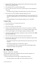
Cross: Red clip to the crossed conductor of one
pair; Black clip to the crossed conductor of the
other pair.
Figure 2
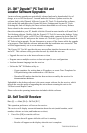
Ground: Red clip to the faulted conductor;
Black clip to ground.
Figure 3
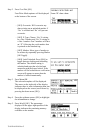
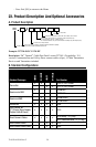
Split: Red clip to Tip of Pair 1; Black clip to
Ring of Pair 1.
Figure 4
Verify Split: Red clip to good conductor of
Pair 1; Black clip to split conductor of Pair 2
Figure 5
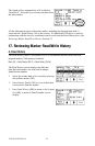
B. Cable Identification
1. Transmitter Setup
1. Connect the 3M
™
Dyna-Coupler to the Transmitter Output Jack [T-6] using the
coupler cable.
Note: Cable Identification requires two 3M Dyna-Couplers: one at the Transmitter
and one at the Receiver.