35
13.11.4 Special Set-Up Procedure (continued)
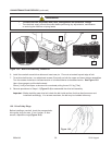
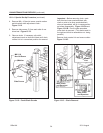
7. Remove fasteners (M8 x 16 socket head screws
and M6 plain washers) that attach column
spacers to machine bed and remove spacers/
outer columns from machine bed. Figure 13-
14A.
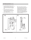
8. Remove fasteners (M8 x 20 socket head
screws) that attach spacers to columns, move
spacer down 100 mm [4 inches] to lower set
of mounting holes and re-attach spacers to
columns. Figure 13-14B.
9. Reverse procedure to reassemble machine.
Note – When installing upper assembly
back into machine (removed in Step 3), slide
upper assembly down into outer columns
until lead screws contact plastic nuts and
support upper assembly. Then, slowly turn
height adjustment crank counterclockwise
until two "clicks" are heard, one at each
plastic nut. Now the upper assembly can be
cranked down (turn height adjustment crank
clockwise) for installation of special nut on
bottom of each lead screw.
Figure 13-14 – Column Spacers/Columns
13-MAINTENANCE AND REPAIRS (continued)
Outer
Column
Outer
Column
Column
Spacer
Column
Spacer
BA
2011 August
800a-NA


