


A90/P90
6
A90/P90
7
English
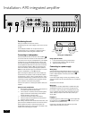
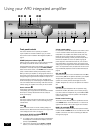
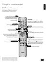
Using your A90 integrated amplier
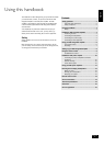
Front panel controls
This section describes how to operate your amplier.
If your amplier has not been installed for you, you should
rst read the section ‘Installation: A90 integrated amplier’ on
page 4.
POWER (and power indicator light)
8
Switches the unit on and off. (You can also switch the amplier
into standby mode with the remote control handset.)
The light indicates the status of the amplier. A red light means
the amplier is in standby mode (press the POWER/STANDBY
button on the remote control, or the POWER button on the front
panel, to switch between standby and powered-up modes).
When you switch your amplier on, the light glows amber for a
few seconds, during which time the speakers are disconnected.
The light changes to green when the amplier is ready for use.
The light may ash if a fault has occurred – the fault type is
shown on the display. You should unplug the amplier and leave
it for a few minutes before reconnecting. If the fault cannot be
cleared, unplug your amplier and contact your Arcam dealer.
Source selectors
2
These buttons select the source connected to the
corresponding input. A light above the relevant button indicates
which input is currently selected and it will also usually be
shown on the display.
VCR
4
This input is similar to the other line level inputs on the amplier
and may be used with a VCR or a second recording unit (e.g.
cassette deck).
TONE
6
Switches the tone circuits on and off, including settings for
individual sources. Note that the tone LED does not light unless
a tone setting has been made. (see page 8).
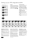
Control knob, SELECT and ENTER
3bobn
The control knob has two functions:
as a volume control, to adjust the output of loudspeakers
and headphones connected to the amplier, and of the
pre-amp output (PRE OUT).
when used in conjunction with the SELECT and ENTER
buttons, to customise amplier settings (see page 8).
Volume control settings
It is important to realise that the position of the volume control
is not an accurate indication of the power delivered to your
loudspeakers. The amplier often delivers its full power long
before the volume control reaches its maximum position,
particularly when listening to heavily recorded compact discs.
However the amplier also has to be capable of giving full
power output from much lower level sources, such as tuners
and cassette decks. Using these sources, the volume control
setting may be much higher before distortion (audible overload)
sets in. To compensate for this, the input levels of each source
may be individually adjusted to avoid accidental overload (see
page 8).
SP1 and SP2
7
These buttons allow you to select and deselect the main (SP1)
and secondary (SP2) set of speakers attached to your amplier.
The light above each button glows if the corresponding
speakers are currently selected. (If both lights are out the
amplier will appear not to work, as all speakers are switched
off!)
PHONES
1
This socket accepts headphones with an impedance rating
between 8Ω and 2kΩ, tted with a 1/4-inch stereo jack plug.
If you wish to listen on headphones only, use the SP1 and SP2
buttons (if necessary) to mute the speakers. The headphone
socket is always active.
Remote control receiver
9
The remote control’s infrared receiver is positioned to the left
of the RECORD button. Ensure the receiver is in a clear line of
sight from the remote control to allow signals to be received.
MODE, UP and DOWN
blbm
These buttons are mainly for use with future optional modules,
however the UP and DOWN buttons are used with the basic A90
amplier to move the cursor when customising the ‘Welcome
message’ (see page 8).
321 6 7 8
9 b
k
A90 INTEGRATED AMPLIFIER
PHONO/AUX CD TUNER AV DVD VCR TAPE TONE SP1 SP2 POWERPHONES
RECORD MODE
ENTER
SELECT
4
5
bl bm bnbo