


welcome contents
installation
&operation
special
configuration
furter
information
6
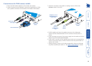
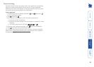
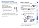
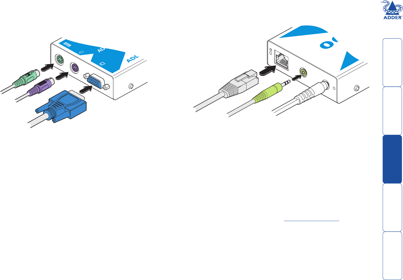
Connections at the X100 (remote) module
1 Place the X100 module adjacent to the remote user location.
2 Attach the video monitor, keyboard, mouse (and, optionally for X100A
users, speaker) connectors to the sockets of the Adder X100 module.
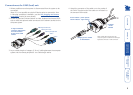
3 Attach the connector of the cable run leading from the CAM to the
TO LOCAL socket of the X100.
From mouse
From keyboard
From video monitor
Adder X100
module
4 (X100A models only) Insert the speaker connector to the light green
coloured socket situated between the link connector and the power in
socket.
5 Insert the output connector of the power supply into the socket at the front
edge of the X100 module labelled POWER.
6 Insert the IEC connector of the supplied power lead into the corresponding
socket of the power supply. Connect the other end of the power lead to a
nearby mains socket.
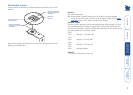
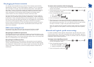
7 Where necessary, use the in-built video compensation feature to eliminate
any effects caused by the cable run. See Video compensation for details.
R
®
www
.adder
.com
TO
LOCAL
PO
WER
From
power
adapter
Category 5, 5e or 6
cable leading to the
CAM module
Adder X100
module
From
speakers
(X100A models
only)