9 Rev. 10©1999 - 2006 DMC Co., Ltd.
A
TP/AST Series Product Specifications
5-5. Mounting Notes
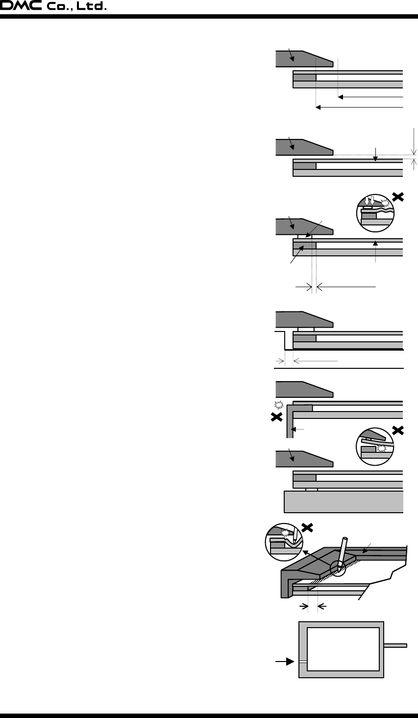
§ Bezel Edge
Bezel edge must be positioned in the area between the Active
Area and the Viewing Area. The bezel may press the
touchscreen and cause input if the edge enters the Active
Area.
§ Gap between the Bezel and Touchscreen
A gap of approximately 0.5mm is needed between the bezel
and the top electrode. It may cause unexpected input if the
gap is too narrow.
§ Cushion
If a cushion is used between the bezel and the top electrode,
the cushion must be free enough to absorb the expansion and
contraction difference between the bezel and the top
electrode. If the cushion is squashed too hard, the expansion
and the contraction difference may cause the distortion to the
top electrode.
The cushion must be positioned more than 1mm outward from
an inside of the insulation area. (Please refer to right figure)
§ Tolerance
There is a tolerance of 0.2 to 0.3mm for the dimensions of the
touchscreen and the tail. A gap must be made to absorb the
tolerance in the case and the connector.
§ Tail
The tail must not be forcibly stressed or bent too hard to avoid
the conduction in the insulated area and wire breaking.
§ Mounting
Touchscreen must be held from the bottom such as the
structure gluing the touchscreen onto the display. If the
touchscreen is glued to the bezel, the adhesion between the
top and bottom electrode is stressed and may come off.
§ Forbidden Area
The area within 2mm from the insulation area is structurally
week for the pressure, espcially for pen use. The film may be
forcibly bent and may cause defection. This area must be
protected by the bezel and input must be avoided.
§ Air Vent
Most of the touchscreens have the air vent to equalize the
inside air pressure to the outside one. The air vent must be
open and liquid contact must be avoided as the liquid may be
absorbed if the lquid is accumilated near the air vent. The top
electlode must not be swelled by the air pressure from inside
of the case.
0.5mm
Top Electrode
Bezel
Bezel
Display
Forbidden Area
Bezel
Bezel
A
ctive Area
Viewing Area
Tai l
0.2 - 0.3mm
Case
Top Electrode
Bezel
Cushion
Insulation Area
Minimum 1mm


