


Document No. DER-S0017A 3 Rev.1.1 ©2008 DMC Co., Ltd.
TSC-34/RU User’s Guide
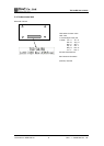
1-3. Peripheral Composition Overview
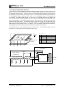
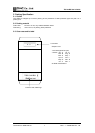
A resistive touch screen is operated by resistance sensitive system between two layers such as film or
glass. Two pieces of transparent materials with conductive coating are placed in the same direction as
two electrodes face each other. The touch screen is activated when these transparent conductive layers
are pressed to contact each other with a finger or a pen. The one of these conductive layers functions as
an X-coordinates electric circuits and the other as a Y-coordinates circuits. To measure the
X-coordinates TSC-34/RU supplies voltage, Vcc to the one of X-coordinates electrodes with GND to the
other. When the touch screen is pressed under this environment the voltage of the X-coordinates resis-
tance is detected by the Y-coordinates electrode (A_in) at the input point (x1), where the X-Y coordinate
resistance layers make contact. The detected voltage in supply side is higher than the GND side, which
means ‘A_in’=Vcc at the point ‘E’ and ‘A_in’=0(*1) at the point ‘A’. TSC-34/RU calculates coordinates
data starting from A/D conversion of the ‘A_in’ voltage. The Y-coordinates is measured in the same way.
By repeating this process alternately, coordinate value at the input point is determined.
(*1) Excluding the loss in the controller circuits and touch screen. Actual detected voltage should be
lower than ‘Vcc - GND’ because of loss happened in the circuitry.
xl A_in
Output Data
A
0V
0000h (Min.)
B 1.25V 00FFh
C 2.5V 01FFh
D 3.75V 02FFh
E 5V 03FFh (Max.)
V
cc
= 5.0V
xl
A
_i
n
X-resistive-layer
Y-resistive-layer
Touch
Vcc
(TSC-30/IC)
E D C B A
(Touch Screen)
(
TSC-34/RU
)
(RS-232C/USB)
To host
Y-resistive-la
y
e
r
X-resistive-layer (reverse side)
x
l
X electrode
(
reverse side
)
Y electrode
Vcc
A
_i
n