Elevation Brake
Replacement
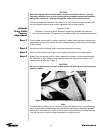
Caution
Step 1
Step 2
The elevation brake replacement procedure is identical to the azimuth brake
replacement. Refer to the previous azimuth procedure for details.
This Procedure Should Only Be Performed In Non-Windy Conditions (Winds
Under 15 mph). When the Brake Is Removed the Antenna Will Be Allowed to
"Freewheel". Two Persons Are Required To Safely Remove and Reinstall the
Brake Assembly. One Person To Perform the Replacement and the Other To Hold
the Antenna In Position.
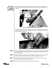
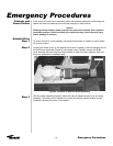
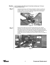
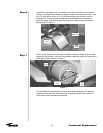
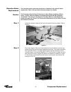
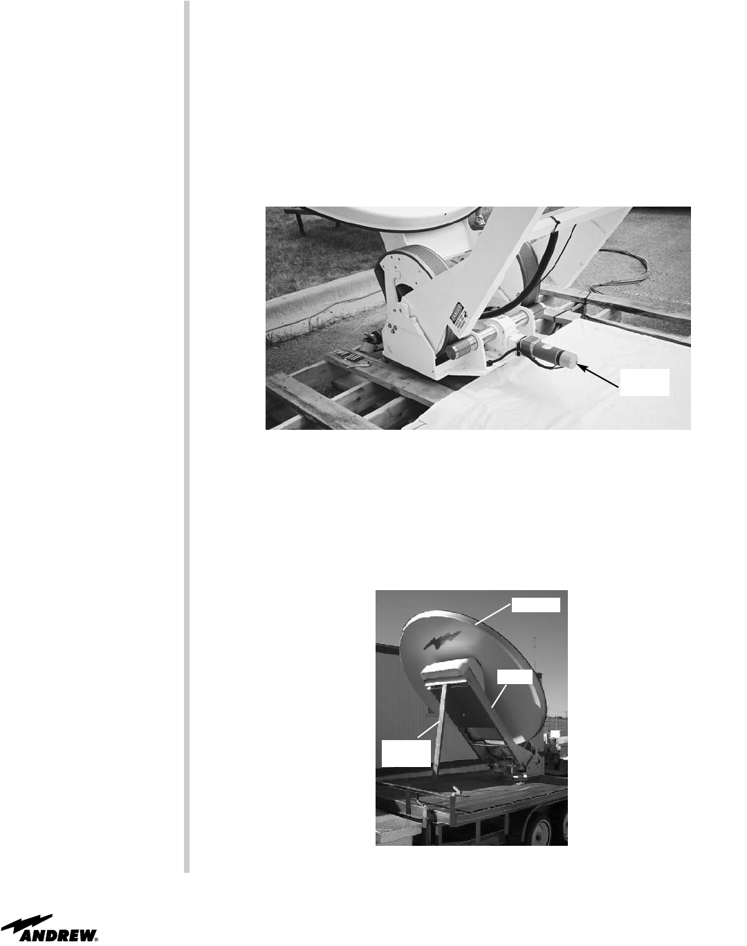
Locate the elevation brake at the front of the azimuth panning frame. Refer to
Figure 8.
Figure 8
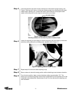
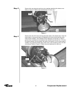
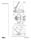
Due to the weight of the boom the elevation boom and reflector must be sup-
ported during the elevation brake replacement process. The antenna elevation
axis should be driven to an angle high enough to provide clearance to work
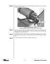
under the boom on the brake assembly. A 2 X 4 inch piece of lumber (or equiv-
alent) should be used to support the boom and reflector as detailed in Figure
9. The elevation axis should be driven down until the boom and reflector are
resting on the 2 X 4.
Figure 9
21
Component Replacement
Elevation
Brake
Reflector
Boom
2 X 4
Lumber


