


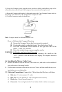
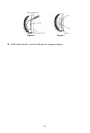
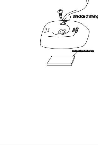
b ) Secure the Compass sensor using the screw provide or double sided adhesive tape to the
selected location with the head of the compass sensor arrowhead facing forward.
c ) Route the Compass cable up the A pillar and connect the 5 pin Compass Sensor cable to
the mating 5 pin connector of the Temperature/ Compass Y cable.
d ) Tuck the connectors under the head liner.
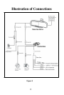
Figure 3
Note: Compass must be calibrated before use.
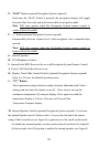
How to Calibrate the Compass Direction
A. Ensure the Compass Sensor has been securely mounted.
B. Position the vehicle so that the front of the vehicle faces North.
C. Press the Calibration Switch located on the right rear side of the
mirror to the “IN” position.
D. Drive the vehicle in one or more complete circles.
WARNING:
Calibration must last at least 10 seconds.
E. Press the Calibration Switch again, returning the switch to the
“OUT” position. Now the mirror will display the compass direction
accurately.
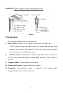
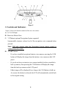
(6) Installing the Mirror Cable Cover
a) Remove the adhesive tape on the base of the cable cover, and stick it to the windshield
next to the mirror’s mounting bracket
b) Put the mirror extension cables on the wire cover’s base, and then install the top cover
into the base to cover both cables.
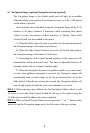
(7) Electrical Connections: Connect the 4 Wires from the filter box as follows:
a) Red wire -12- volt constant (+12 volts)
b) Blue wire
-12-volt ignition (12 volts with ignition on switch on)
c) Black wire - Chassis ground (negative)
d) Green wire - Reverse light switch (12 volt when vehicle is in the reverse gear)
6