


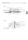
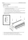
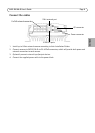
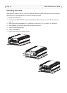
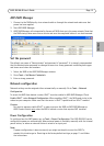

AXIS Q8108-R User’s Guide Page 7
ENGLISH
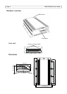
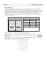
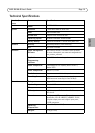
Pin assignment - I/O connector
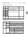
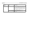
LED indicators
Pin
number
Function Notes Specifications
1 Output 1 Open collector NPN transistor with the emitter
connected to ground when activated.
Outputs are reserved for developer use.
Max load = 500mA
2Output 2
3 Input 1 Inactive for voltages less than 1V
Active for voltages more than 3V
Only one input can be programmed via AXIS NVR
manager, see Power Configuration, on page 13
Max input = + 30V
4Input 2
5Input 3
6Input 4
7Input 5
8Input 6
9Input 7
10 Input 8
11 5V DC
Power
Can be used to power auxiliary equipment.
Note:
This pin can only be used as power out.
Max load = 250mA
12 GND Ground
LED Color Indication
Network Amber Link established.
Green
Unlit
Steady for connection to 100 Mbit/s network
For connection to 1Gbit/s network
Power Green Power supplied - normal operation.
Green and
Amber
Battery powered
Unlit Power off
PoE/Link Green Steady Power is being supplied to the camera
Flash slowly Short circuit
2 flash sequence Error in PoE connection.
5 flash sequence Connected units exceed the max load.
6 flash sequence Connected units in the left or right group
exceed the max load.
Amber Link established