


232SPS24595 Manual Appendix A A-1
B&B Electronics -- PO Box 1040 -- Ottawa, IL 61350
PH (815) 433-5100 -- FAX (815) 434-7094
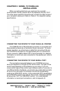
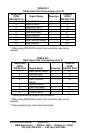
APPENDIX A: PARALLEL PORT CONNECTIONS
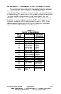
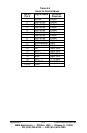
The parallel port connections for the parallel to serial and serial
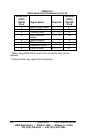
to parallel mode are shown in Table A-1, and Table A-2,
respectively. The connections required are the same for both modes
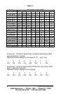
of handshaking. The error lines on the parallel port are forced to the
"no error" states. If the printer is off-line, out of paper, etc., the
232SPS2 will force the busy line (Pin #11) on the parallel port high
(logic "1") when in parallel to serial mode. If a error occurs in serial
to parallel mode, the XOFF character will be sent or DTR will be
lowered depending on type of flow control used. (NU - Indicates a
signal is not used or is not “passed through”)
Table A-1
Parallel to Serial Mode
DB-25
Pin #
Signal Name 232SPS2
Direction
1 Strobe Input
2 Data bit #0 Input
3 Data bit #1 Input
4 Data bit #2 Input
5 Data bit #3 Input
6 Data bit #4 Input
7 Data bit #5 Input
8 Data bit #6 Input
9 Data bit #7 Input
10 Acknowledge Output
11 Busy Output
12 PE "0" Output
13 SLCT “1” Output
14 Auto Feed Input (NU)
15 Error "1" Output
16 INIT Input (NU)
17 SLCT IN Input (NU)
18-25 GND