


B-2 Appendix B 232SPS24595 Manual
B&B Electronics -- PO Box 1040 -- Ottawa, IL 61350
PH (815) 433-5100 -- FAX (815) 434-7094
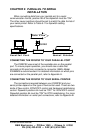
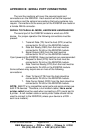
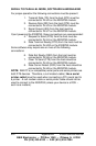
SERIAL TO PARALLEL MODE, SOFTWARE HANDSHAKING
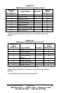
For proper operation the following connections must be present:
1. Transmit Data (TD) from the host (DTE) must be
connected to Pin #2 on the 232SPS2 module.
2. Receive Data (RD) from the host (DTE) must be
connected to Pin #3 on the 232SPS2 module.
3. Signal Ground (SG) from the host must be
connected to Pin #7 on the 232SPS2 module.
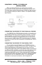
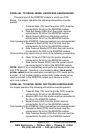
If port powering the 232SPS2, these connections are recommended:
4. Request to Send (RTS) from the host must be
connected to Pin #4 on the 232SPS2 module.
5. Data Terminal Ready (DTR) from t he host must be
connected to Pin #20 on the 232SPS2 module.
Some software may require one or more of the following
connections:
6. Data Set Ready (DSR) from the host must be
connected to Pin #6 on the 232SPS2 module.
7. Clear To Send (CTS) from the host should be
connected to Pin #5 on the 232SPS2 module.
8. Data Carrier Detect (DCD) from the host should be
connected to Pin #8 on the 232SPS2 module.
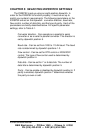
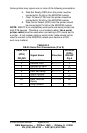
NOTE: IBM PC’s (or compatible) serial ports and serial printers are
both DTE devices. Therefore, a null modem cable ( like a serial
printer cable!) must be used when connecting a PC’s serial port to
a printer. A null modem cable or serial printer cable should not be
used to connect to the 232SPS2 (unless your device is a DCE --
such as a modem).