


4
5
L INK F AULT D ETECTION F EATURE
Link Fault Detection is only available when using Force-10 or Force-100
mode; it is not available in Auto-Negotiation mode. When LFD is enabled and
the input link is down at one interface to the 10/100 Autosensing Media
Converter, the transmitter output on that interface is turned off for about
425ms every 3.8 seconds (i.e. blinking). It applies to both network interfaces
and to both data rates. If the link at the other interface to the 10/100
Autosensing Media Converter is also down, there is no output. LFD causes the
Link Up indicator of the link partner to blink.
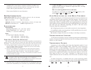
When the 10/100 Autosensing Media Converter is in one of the Force
modes, enable LFD by setting S5
to the ON position. Disable LFD (default) by
setting S5
to the OFF position. In order for LFD to function properly, Force
mode must be enabled by setting S7
to ON with either S8 ON for 10 Mbps or
S8 OFF
for 100 Mbps. NOTE: S6 must also be ON when enabling LFD.
T WISTED P AIR C ROSSOVER/PASS-THROUGH S WITCH
The 10/100 Autosensing Media Converter features a crossover/pass-through
push-button switch, located on the faceplate next to the RJ-45 connector, to
set the twisted pair connection type (see page 1 for illustration of location).
Select a pass-through connection by pressing the push-button IN. A cross-
over connection is selected when the push-button is OUT. If you are not sure
which connection is needed, set the push-button to whatever setting makes
the twisted pair LNK (link) LED glow.
LED Indicators
The 10/100 Autosensing Media Converter features several diagnostic LEDs
per port. The LED functions for the media converter are:
T WISTED P AIR P ORT
LNK Glows green when a twisted pair link is established.
ACT Glows yellow when data is detected on the port.
100 Glows yellow when 100 Mbps data is detected on the port.
LFD Glows green when Link Fault Detection is enabled.
(NOTE: This feature is only available when either Force -10 or Force-100 mode is
enabled. Refer to the LFD LED Activity section for more information.)
AN Glows green when Auto-Negotiation/PNP mode is enabled.
PWR Glows green when unit has power.
NOTE
When using the LFD feature, if the DIP switches are in any other combination than
listed above, your 10/100 media converter may exhibit erratic behavior.
F IBER P ORT
100 Glows yellow when 100 Mbps data is detected on the port.
ACT Glows green when data is detected on the port.
LNK Glows green when a fiber link is established.
L INK F
AULT D ETECTION LED ACTIVITY
When LFD is enabled and a fault occurs on a segment of the media
conversion, the various Link LEDs in that conversion will either blink or
extinguish. LEDs may react differently depending on the type of end devices
in the conversion, whether the 10/100 Autosensing Media Converter is in
Force-10 or Force-100 mode, where the fault occurs, etc. For questions,
please contact Technical support.
Installation Troubleshooting
• During installation, first test the fiber and twisted pair connections with all
troubleshooting features disabled, then enable these features, if desired, just
before final installation. This will reduce the features’ interference with
testing.
• When working with units where the features cannot be disabled, you must
establish BOTH your twisted pair and fiber connections before the link LEDs
will light!
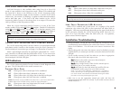
• To test a media converter by itself, first make sure you have an appropriate
fiber patch cable, then follow these steps to test:
SStteepp
11::
Connect the media converter to the twisted pair
device with a twisted pair cable.
SStteepp
22::
Loop a single strand of fiber from the transmit port to
the receive port of your media converter.
SStteepp
33::
Verify that you have both twisted pair and fiber link (see
LED Operation section, page 4)) on your media converter.
NOTE: Use caution when conducting a loopback test; it is possible to
create a network loop if connecting the media converter’s twsited pair port
to an active network. IMC Networks recommends connecting the twisted
pair cable to a PC when performing this type of test.
• Make sure to use the appropriate twisted pair cable, and have the
crossover/pass-through switch set correctly if your media converters do not
include AutoCross.
NOTE
Twisted pair AND fiber optic cables must be connected, and the twisted pair crossover/
pass-through switch set correctly, before either LNK LED will glow solid.