


15
APPENDIX: Pinouts
Appendix: Pinouts
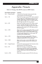
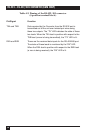
Table A-1. Pinning of the RS-232 connector (DB25 female).
Pin Number and Signal Function
Pin1 — Frame Ground Connects the Converter’s frame ground to the
frame ground of the RS-232 device.
Pin 2 — TD When the Converter is set to DCE, data is received
on Pin 2 and the TX LED lights up when Pin 2 is a
“space” (logical zero). When the Converter is set
for DTE, data is output on Pin 2, in which case the
RX LED lights up when Pin 2 is a “space.”
Pin 3 — RD When the Converter is set for DCE, data is output
on Pin 3. The RX LED lights up when Pin 3 is a
“space.” When the converter is set for DTE, data is
received on Pin 3 and the TX LED lights up when
Pin 3 is a “space.”
Pin 4 — RTS When the Converter is set for DCE, RTS is an input
which turns on the RS-422/485 driver when true.
When the Converter is set for DTE, RTS is always
an output and is always true. (In DTE mode, CD
controls the RS-422/485 driver.)
Pin 5 — CTS When the Converter is set for DCE, CTS is an
output that follows the RTS/DTR input. When the
converter is set for DTE, CTS is not used.
Pin 6 — DSR When the Converter is set for DCE, DSR is true.
When the Converter is set for DTE, DSR is not
used.
Pin 7 — Signal Ground Connects the signal ground of the Converter to the
signal ground of the RS-232 device.
Pin 8 — CD When the Converter is configured DCE, CD is
always true (and RTS controls the RS-422/485
driver). When the Converter is set for DTE, CD is
an input which turns on the RS-422/485 driver
when true.
Pin 20 — DTR When the Converter is set for DTE, Pin 20 is true.