


Chapter 4: Operation
Page 8 724-746-5500 | blackbox.com LMC009A-R5
4. Operation
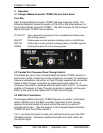
4.1 Compact Media Converter TP/BNC 50-ohm Front Panel
The LEDs
Each Compact Media Converter TP/BNC features diagnostic LEDs. The
following illustration shows the location of the LEDs, and other features, on
the Compact Media Converter TP/BNC. The LED functions for the Compact
Media Converter TP/BNC are as follows:
TP LNK/ACT Glows yellow when a twisted pair link is established and flickers when
data is being received
BNC ACT Flickers green in normal operation indicating activity on the BNC port
BNC COL Flickers red in normal operation indicating activity on the BNC segment
POWER Flickers yellow when the unit is receiving power
4.2 Twisted Pair Crossover/Pass-Through Switch
The twisted pair port on the Compact Media Converter TP/BNC features a
push-button switch, located next to the twisted pair connector, for selecting a
crossover workstation connection or Pass-Through repeater/hub connection.
Select a Pass-Through connection by pressing the push-button IN. A
Crossover connection is selected when the push-button is OUT. If uncertain
whether a Crossover or Pass-Through connection is needed, set the push-
button to the position that makes the TP LNK (link) LED glow.
4.3 BNC Port Termination
The Compact Media Converter TP/BNC features a 2-position, termination
switch (TERM) next to the BNC connector that allows a think coaxial
segment to be terminated at the port without the use of an external ‘T’
connector/terminator. (See the diagram in the Compact Media Converter
TP/BNC 50-ohm Front Panel section.)
If a ‘T’ connector/terminator is used, this switched must be set in the OFF
(disabled) position. Otherwise, double termination will result, which will
corrupt the signal.