


Page 10
724-746-5500 | blackbox.com
Chapter 2: Overview
2.5 Hardware Description
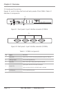
Figures 2-1 and 2-2 show the front and back panels of the IC292A. Table 2-1
describes its components.
1 2 3
4
Figure 2-1. Front panel: 4-port interface converter (IC292A).
5
Figure 2-2. Back panel: 4-port interface converter (IC292A).
Table 2-1. IC292A components.
Pin Signal Direction
1 Power LED Lights when the hub is properly powered through the USB port.
2 USB Type B port Links to USB Type B device.
3 Data LEDs Blinks when data is being transmitted or received.
4 Mode LEDs
Lights green when RS-232 mode is selected.
Lights red when RS-422 or RS-485 mode is selected.
5 (4) DB9 ports Links to serial device ports.