28
Reference
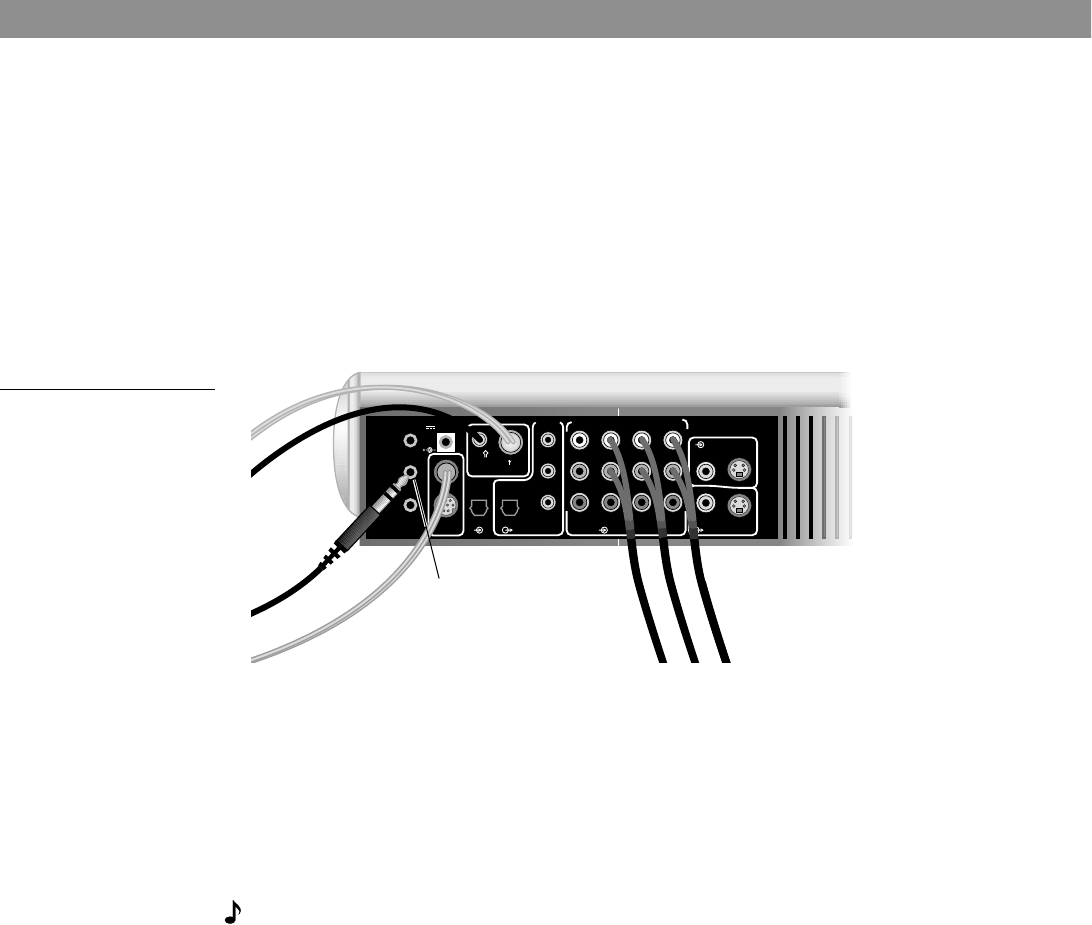
Connecting the optional IR emitter cable
The IR (infrared) emitter cable is designed for optional use with system components that are
connected to the media center, but placed where they cannot receive IR signals from it. This
can resolve the problem when a particular component does not respond to LIFESTYLE
®
remote control commands.
By plugging an emitter into the media center and placing it near the component, you can
make sure that the LIFESTYLE
®
remote control signals reach that component.
To use the emitter:
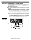
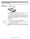
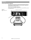
1. Insert the 3.5 mm plug into the IR EMITTER jack on the rear of the media center
(Figure 27).
Figure 27
Optional IR emitter cable
connection to the media
center
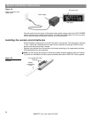
2. Place the flat side at the other end of the cable against the IR receiver window on the
front of the component.
Note: There is a procedure you must follow to program the LIFESTYLE
®
remote so that it
works with your other components. Refer to the LIFESTYLE
®
Operating Guide for details on
how to do that.
3. Confirm that IR signals now work to control that component. Move the emitter around, as
necessary, to find the best position.
4. Use the double-sided tape enclosed with the emitter to affix it in the proper position.
Note: If you have questions, or need to obtain a replacement emitter, contact Bose
®
cus-
tomer service. Refer to the Bose address list included with your system.
Accessories
For information on speaker mounting brackets and stands, additional remote controls, and
connecting additional Bose powered loudspeakers, contact your Bose dealer or call Bose
customer service.
Warranty
Your LIFESTYLE
®
home entertainment system is covered by a transferable limited warranty.
See your warranty card for details. Please be sure to fill out the information section on the
card and mail it to Bose.
Contacting customer service
For additional help in solving problems, contact Bose customer service. See the address and
phone number list provided with your system.
TV
SENSOR
IR
EMITTER
SERIAL
DATA
SPEAKER
ZONES
1
2
1.1A
33V DC POWER
AM
FM 75
ANTENNA
OPTICAL OPTICAL
INPUT
OUTPUT
AUDIO OUTPUTS
DIGITAL DIGITAL
R
L
RECORD
DIGITAL
R
L
DIGITAL
R
L
DIGITAL
R
L
DIGITAL
R
L
TAPE
AUDIO INPUTS
AUX VCR TV
VIDEO INPUTS
COMPOSITE S-VIDEO
COMPOSITE S-VIDEO
VIDEO OUTPUTS
IR EMITTER
jack
AM259777_02_V.pdf • April 23, 2002


