


EdgeAccess
®
Universal Chassis System
6002/6003/6004 WWDM Users Manual
3-2
3.2 Operation of the Stand Alone Models
To ensure proper optical performance levels, you will need to determine the loss budget. This
factor will ensure link integrity and ample signal strength at the remote end of your link.
To operate the 6002 stand alone model:
Step 1 Measure each of the optical composite fiber links at the lowest wavelength of operation.
This will determine the limiting factor in the loss budget. Each Tx device attached to the
WDM (Wavelength Division Multiplexer) has a loss budget that was specified by the
manufacturer. This specified loss budget must be greater than the measured loss of the
fiber link, plus the additional attenuation of the WDM. For applicable channel and
wavelength specifications, see the tables in Chapter 6.
Example for a Model 6002, 1310/1550 WWDM:
The composite link has an 8dB loss measured at 1310nm. The device attached to the
1310nm channel has a stated loss budget of 15dB. The 6002 1310/1550nm model has a
maximum end-to-end attenuation of 2dB for a pair of units on SMF (single mode fiber).
Factor in approximately 1dB for the additional connector loss from the patch cables
between the 6002 and the local devices. This would result in a safety margin of
approximately 15dB – (8dB + 2dB + 1dB) = 4dB.
Note: When connecting any device, pay attention to the proper wavelength channel.
Step 2 Attach one (1) composite fiber link cable to the connector marked "Remote Tx" on the
local WDM and "Remote Rx" on the remote WDM. Refer to the WWDM Installation
Diagram in Figure 4 for connection orientation.
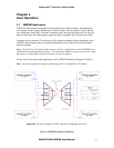
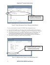
Step 3 Check the installation. The equipment is now ready to transmit the optically multiplexed
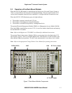
signals. Figures 5 and 6 represent the non-powered 6002/3/4 stand alone models.
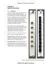
Figure 5. Model 6000 Stand Alone (Front View)
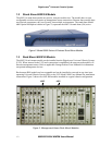
Figure 6. Model 6002 Stand Alone (Rear View)