


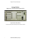

EdgeAccess
®
Universal Chassis System
6002/6003/6004 WWDM Users Manual
2-1
Chapter 2
Set-up and Installation
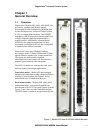
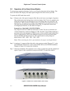
2.1 Unpacking and Installing the Stand Alone Models
Each stand alone 6002/3/4 is factory tested and shipped in protective cartons. After unpacking the
unit and its accessories, retain the shipping carton and protective packing material in the event a
need arises in which the equipment must be returned to the factory. SA models can be installed on
any desktop, shelf, or mounted in a rack with the optional rack mount bracket kit.
Note: Before mounting a stand alone model, keep in mind that the operator must have access to
the rear of the unit for optical cable attachments.
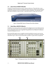
2.2 Unpacking and Installing the Rack Mount Models
Each rack mount 6002/3/4 is factory tested and shipped in protective cartons. After unpacking the
unit and accessories, retain the shipping carton and packing materials. In the unlikely event that a
need will arise, these items should be used to return the module to the factory.
Recommended installation sequence:
• Complete the installation of the EdgeAccess Universal Chassis System first. Refer to the
UCS Model 1000 Users Manual for complete installation and operating instructions.
• If the Domain Management Module (DMM) is to be included in the UCS, it should be
installed prior to the 6002/3/4 models.
• If the Chassis Interconnect Module (CIM) is to be employed, it should be installed in the
UCS prior to the 6002/3/4 models.
Note: See the appropriate EdgeAccess Users Manual for additional installation instructions.
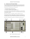
2.3 Installing Modules into a UCS Chassis
Rack mount models can be inserted into the EdgeAccess Universal Chassis System at any time.
The UCS connector interface will detect installed RM modules. System rebooting is not required.
Note: Never force the module into a chassis slot, as damage to the connector pins may occur.
Install the 6002/3/4 RM model into an available UCS slot:
• While sliding the hot-swappable module into position, you will feel and hear the module
connect firmly with the backplane. It should fit snugly into the connector.
• Hand-tighten the knurled knobs, which will fasten the module in place. The use of a
screwdriver is not necessary, nor recommended.
When a module is inserted into an active UCS, the 6002/3/4 model’s LED will display to verify
that a connection is made. If an installed DMM is operational, it will detect the presence of all
inserted modules. The DMM will display the modules status on appropriate software screens.
See Chapter 4 for software interaction.