


6
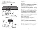
Attach the IR emitter
directly over the IR
sensor.
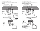
Sample System Diagram 3:
Transmitting S-video and DTS from a DVD
600 feet with IR
LEFT
300mA
15VDC
POWER
IR REPEATERS
800
1000
600400
0
200
CAT-5
VIDEO OUT
DIGITAL OUT
AUDIO OUT
VIDEO IN
DIGITAL IN
AUDIO IN
RIGHT COAX OPTICAL
LENGTH
ADJUST
(in feet)
VIDEO S-VIDEO
PCM/AC3/DTS
POWER
LEFT
AUDIO
RIGHT DIGITAL
AUDIO COAX
VIDEO S-VIDEO CAT-5 IR INPUT
800
1000
600400
0
200
Set LENGTH ADJUST to 600
Connect a local monitor here
Connect a local receiver here
DVD
600 feet CAT-5
Digital
Surround Sound
Processor
TV
350-103 power
supply (included)
2132
2171
Digital
audio
s-video
350-103 power
supply (included)
3
FEATURES
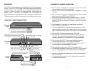
EASY WIRING
The SVC-10 transmitter and receiver communicate over a single
run of CAT-5 wire. A back panel control is on the transmitter to
allow compensation for any length of wire up to 1000 feet. Wire
RJ-45 connections according to TIA T568A standard.
FLEXIBLE VIDEO INPUT
Choose between s-video input or composite video. The SVC-10
has its own connector for each - no need for a converter plug.
UNIVERSAL AUDIO
The SVC-10 accepts either left&right analog audio or digital
audio. It can handle either coax or fiber optic (TOSLINK) digital
audio. When using the fiber optic cable, the SVC-10 converts
this signal and puts it on the coax digital loop out connector.
When using analog audio, the SVC-10 will maintain Dolby Pro-
logic® encoding if present.
LOOP OUT CONNECTORS
All SVC-10 connectors have built in loop through connectors for
a second device such as a local monitor.
ACTIVE TERMINATE FEATURE
The SVC-10 terminates the inputs into a 75 ohm load. When a
second cable is connected to the output, the SVC-10
automatically disconnects this termination to allow the second
device to provide the termination.
IR CONTROL
Standard 12 volt ChannelPlus IR targets and emitters can be
used with the SVC-10 to allow control of the source from the
remote location.
MOUNTING
The SVC-10 can be mounted in standard 19” racks by attaching
the included mounting ears. Remove the rubber feet on the
bottom of the unit to ensure clearance when inserted into a rack.