


MSS6000 Installation Instructions
6
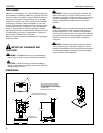
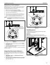
Site Preparation for Mounting to Surface
WARNING: EXCEEDING WEIGHT CAPACITY CAN
RESULT IN SERIOUS PERSONAL INJURY OR DAMAGE
TO EQUIPMENT! It is the installer’s responsibility to make
sure the combined weight of all components does not exceed
150 lbs (68.04 kg).
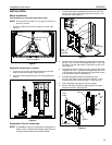
CAUTION: TURNING DISPLAY CAN CAUSE DAMAGE
TO SURROUNDING OBJECTS. Make certain location
provides enough area for the display to rotate +
45° without
being obstructed.
NOTE: See Display Swivel Stop Location Adjustment
section for information on adjusting rotation.
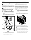
1. Locate a flat dry surface on which to mount the MSS6000
assembly.
2. Measure the hole locations on bottom of MSS6000 and
mark the four mounting hole locations on mounting surface.
(See Figure 5)
Figure 5
3. Drill four 1/4" diameter holes through mounting surface at
marks.
4. Secure mount to mounting surface using four 1/4-20 cap
screws (not provided) with a length equal to the thickness of
the mounting surface A plus 3/4". (See Figure 5)
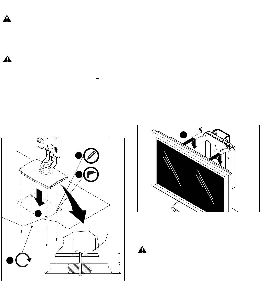
Display Installation
The following procedure assumes that the proper interface
bracket for the display being mounted has already been
installed on the display.
If no interface bracket is present on display, install bracket to
display using the instructions included with the interface bracket
before proceeding.
If an interface bracket for the display being mounted needs to
be obtained, or additional assistance is required, contact a
Chief Customer Service representative.
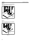
NOTE: If the display being mounted has a height of more than
24" the mount needs to be modified prior to display
installation. (See Display More Than 24 Inches High
section.)
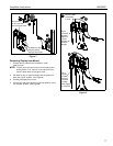
To install the display:
1. While supporting both sides of display, align four mounting
buttons on display or interface bracket with four mounting
holes in faceplate. (See Figures 6 & 7)
Figure 6
2. Lower display into place listening for audible "click" to
ensure recessed area of mounting buttons are properly
seated in lower area of mounting holes. (See Figures 6 & 7)
WARNING: IMPROPER INSTALLATION CAN LEAD TO
DISPLAY FALLING CAUSING SERIOUS PERSONAL
INJURY OR DAMAGE TO EQUIPMENT! Ensure mounting
buttons are completely engaged in mounting holes.
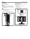
NOTE: Holes are provided in the faceplate for use with a
padlock or similar locking device, if desired. In addition,
the pin and nut may be removed from the upper holes
and moved to the lower holes for use as a more
permanent locking device. (See Figure 7)
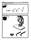
x 4
1
x 4
4
MSS6000
3/4"
A
x 4
2
3
1