


PCM SERIES Installation Instructions
4
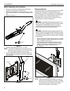
Mount Assembly and Installation
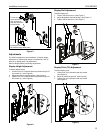
1. Fold tube out until tube mounting bracket rests against
faceplate mounting bracket. (See Figure 2)
2. Secure tube to faceplate mounting bracket using 3/16" hex
wrench (C) and two 5/16-18 x 1/2" button head cap screws
(D).
3. Tighten all hardware.
Figure 2
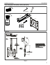
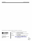
4. Thread the tube assembly (A) onto 1-1/2” NPT.
NOTE:
The product is suitable for use with a Listed ceiling
plate which can accommodate 1-1/2" NPT pipe, and
has a rated weight capacity of 200 lbs (91 kg).
5. Secure faceplate (B) to faceplate mounting bracket using
3/16" hex wrench (C) and four 5/16-18 x 1/2" button head
cap screws (D).
Figure 3
Display Installation
If the mounting pattern of the display being installed is a VESA
standard 200 x 200 pattern the mounting buttons can be
installed directly to the back of the display. If the display has any
other mounting pattern an interface bracket must be obtained
before proceeding. Consult a Chief Customer Service
representative if an interface bracket is required by calling
1-800-582-6480 or visit www.chiefmfg.com.
WARNING:
IMPROPER INSTALLATION CAN LEAD TO
MOUNT FALLING CAUSING SEVERE PERSONAL INJURY
OR DAMAGE TO EQUIPMENT. Displays can weigh in
excess of 40 lbs (18.1kg). ALWAYS use two people and
proper lifting techniques when installing display.
WARNING:
IMPROPER INSTALLATION CAN LEAD TO
MOUNT FALLING CAUSING SEVERE PERSONAL INJURY
OR DAMAGE TO EQUIPMENT. Make sure mounting buttons
on display are properly seated in mounting holes in faceplate.
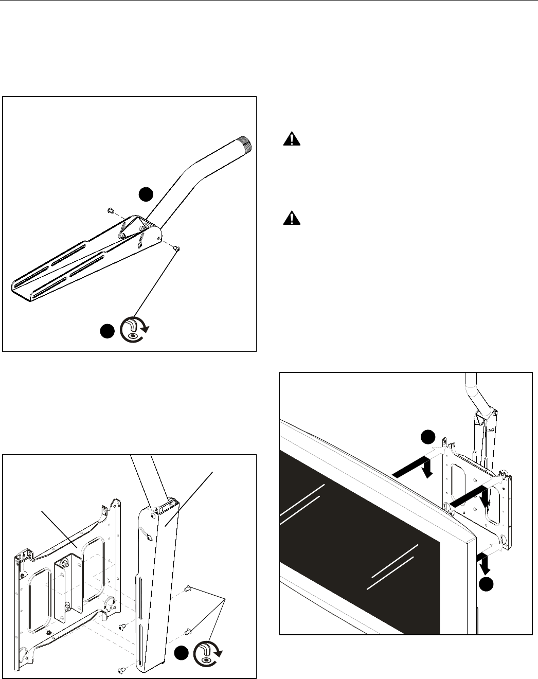
To install display:
1. While supporting both sides of display, align four mounting
buttons on display or interface bracket with four mounting
holes in faceplate. (See Figure 4)
2. Lower display into place listening for audible "click" to
ensure recessed area of mounting buttons are properly
seated in lower area of mounting holes and "click lock"
mechanism has engaged. (See Figure 4) and
(See Figure 5)
Figure 4
NOTE:
Holes are provided in the faceplate for use with a
padlock or similar locking device, if desired. In addition,
the pin and nut may be removed from the upper holes
and moved to the lower holes for use as a more
permanent locking device. (See Figure 5)
1
(D) x 2
2
5
(A) x1
(D) x4
(B) x 1
2
1