


2-Series Professional Media Controller Crestron MC2E
Description
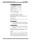
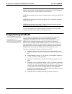
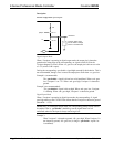
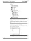
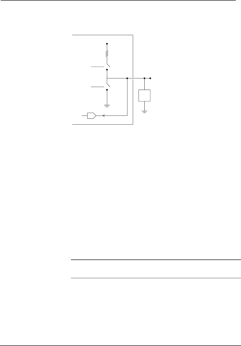
Internal configuration of a Versiport
+5V
2K
pullup1
o1
S1-A
S1-B
A
Used for analog input.
Can be either a voltage
source or resistive load.
VersiPort 1
Digital Output Mode
When a Versiport is operating in digital output mode, the output pin is shorted to
ground on the rising edge of the corresponding <o> signal (switch S1-B in the
Versiport diagram is closed). When <o> goes low, the output pin is driven to a value
of +5V (switch S1-B is open).
Driving the corresponding <pu-disable> signal high can modify this behavior. This is
not recommended, though, since it causes the output pin to float when <o> goes low.
Example 1 (recommended):
The <pu-disable1> signal is driven low or left undefined. When <o1> goes
low, Versiport 1 is at +5V. When <o1> goes high, Versiport 1 is shorted to
ground.
Example 2 (not recommended):
The <pu-disable1> signal is driven high. When <o1> goes low, Versiport
1 is floating. When <o1> goes high, Versiport 1 is shorted to ground.
Digital Input Mode
When a Versiport is operating in digital input mode, the corresponding <i> signal
goes high whenever the C2I-MC2-IO4 detects that the Versiport is shorted to ground
(threshold < +2.5V).
NOTE: Here, as with digital output mode, the corresponding pullup resistor should
be enabled. That is, <pu-disable> should be given the signal name 0 or left
undefined; otherwise the input is always read as logic low.
Example 3:
When Versiport 3 is shorted to ground, <i3> goes high. When Versiport 3 is
not shorted to ground, <i3> goes low (so long as <pu-disable> equals 0 or
is undefined).
28 • 2-Series Professional Media Controller: MC2E Operations Guide - DOC. 6142