


11
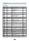
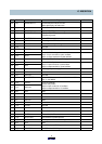
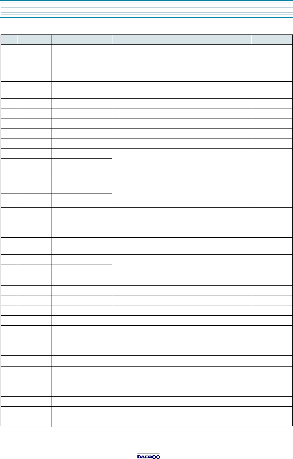
26 P4(7) AUDIO MUTE H Connect this port to 95 pin of ICY01.
When special play, set audio mute.
27 P4(6) Not used
28 P4(5) REC LED H Light up LED(RED) when recording
29 P4(4) TIMER REC LED H Light up LED(GREEN) when ready to
programming record.
30 P4(3) MONITOR ON H When CRT on, set "H".
31 P4(2) VCR ON H Recording when CRT off, set "H"
32 P4(1) RELAY ON H When CRT on, relay on during 1sec.
33 P4(0) Not used
34 RESET RESET(L) RESET
35 P3(1) Xcin It uses 32.768KHz Crystal.
35 pin is input terminal for crystal oscillator
36 pin is output terminal for crystal oscillator
36 P3(0) Xcout
37 Vcc Vcc
Ever +5V(
±
0.5V). Positive power supply
38 Xin Xin It uses 16MHz Crystal.
38 pin is input terminal for crystal oscillator
39 pin is output terminal for crystal oscillator
39 Xout Xout
40 Vss Vss GND Negative power supply.
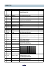
41 P2(2) OSCin3 Not used
42 P2(1) OSCout3 Not used
43 CLK SELECT When MICOM to start, decide to 32.768KHz or 16MHz.
Set "L" : 32.768KHz
44 P2(0) OSCin2 It uses LC oscillator.
Set the OSD position.
38 pin is input terminal for LC oscillator
39 pin is output terminal for LC oscillator
45 P1(7) OSCout2
46 NUB NUB GND
47 P1(6) LP H Not used
48 P1(5) FSC IN Not used
49 Vcc OSD Vss GND
50 P1(4) CVS IN Not used
51 P1(3) LECHA Not used
52 P1(2) Not used
53 Vcc OSD Vcc
Ever +5V (
±
0.5V).
54 P1(1) FILTER Filter terminal for PLL.
55 P1(0) SLD FILTER Filter terminal for SYNC separate.
56 P0(7) C.V.S IN For Caption and Parental control signal detect.
57 NUA NUA GND
58 P0(6) H SYNC IN For OSD horizontal SYNC input
59 P0(5) V SYNC IN For OSD vertical SYNC input
Pin Terminal Name Explanation Remarks
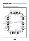
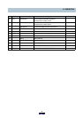
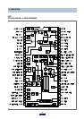
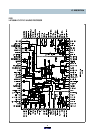
IC DESCRIPTION