12
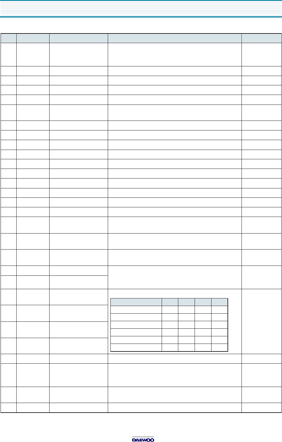
60 P0(4) OSD BLANK OUT Fast blanking control signal.
Switch TV image signal and
Caption/OSD image signal.
61 P0(3) Not used
62 P0(2) OSD B OUT Blue output terminal of OSD image.
63 P0(1) OSD G OUT Green output terminal of OSD image.
64 P0(0) OSD R OUT Red output terminal of OSD image.
65 P10(7) S DATA IIC data I/O.
Control VCR Y/C, TUNER, EEPROM
66 P10(6) Not used
67 P10(5) S CLOCK IIC clock output
68 P10(4) CAP PG mon Not used
69 P10(3) DRUM PG mon Not used
70 P10(2) DRUM FG mon Not used
71 P10(1) M CLOCK IIC clock output
72 P10(0) M DATA IIC data I/O. Control CHROMA IC
73 P9(7) LD F/R Loading Motor Forward(L)/Reverse(H)
74 P9(6) LD ON When operate Loading Motor, set "H"
75 P9(5) PWM2 Not used
76 P9(4) CAPSTAN PWM Control rotate speed of Capstan Motor.
Period of PWM : 23.4KHz
77 P9(3) DRUM PWM Control rotate speed of Drum Motor. Period of PWM :
23.4KHz
78 P9(2) POWER FAIL Input "L", MICOM is Hold mode.
Backup time approx. 30minute.
79 P9(1) RLS IN Supply reel/Take up reel pulse input terminal.
Use to check the Tape remain or
high speed rewind and fast forward.
80 P9(0) RLT IN
81 P8(7) CAM D CAM detection input terminal.
82 P8(6) CAM C
83 P8(5) CAM B
84 P8(4) CAM A
85 P8(3) Not used
86 P8(2) REC SAFETY SW L Recordable tape insert, "L" input.
If "H" input when insert cassette tape,
then automatic play.
87 CAP PG IN Capstan Pulse Generator signal input.
Feed back Capstan rotation speed.
88 Vss AMPVss GND
Pin Terminal Name Explanation Remarks
MODE A B C D
EJECT L H H H
STAND BY L H L H
REV H H L H
STOP H H H L
PLAY H H H L
FF/REW H L H L
IC DESCRIPTION


