


5
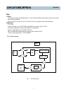
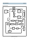
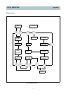
C. PB mode
a) Luminance Signal Processing
The recorded signal is picked up by the head, and amplified 60dB by PRE AMP part.
The amplified FM signal is supplied to FM AGC.
It is automatically controlled by FM AGC to adjust output tolerance of CH1 and CH2.
This signal is FM EQ and phase compensation
It is sent to Double Limiter circuit which removes AM noise, prevents over-modulation and lets the signal input to
FM DEMOD.
The signal from FM DEMOD is fed to main de-emphasis through SUB LPF, and the boosted high frequency in
REC mode is de-emphasized there, and input to pin 20 through pin 21.
After eliminating demodulation noise caused during the above processes by 3M LPF, it is input to YNR circuit.
The signal passing through YNR is supplied to non-linear emphasis circuit.
Non-linear de-emphasis plays a role quite opposed to Non-linear emphasis in record mode.
That is, it de-emphasized the high frequency level emphasized by Non-linear emphasis.
Double noise canceller reduces minute noise of video signal.
After being passed it is mixed with color signal.
The mixed signal is obtained pin 29, supplied to pin 17 of I501.
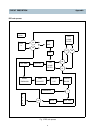
b) Color Signal Process
The 60dB amplified signal in PRE AMP goes to 1.3MHz LPF, which separates down converted color signal. And
then it is supplied to AGC part.
ACC(Automatic Color Control) AMP stabilizes the color signal .
The stabilized signal is supplied to main converter and mixed with the 5.06MHz signal come from sub-converter.
Its output is 5.06MHz
6
27KHz. The mixed signal is fed to 4.43MHz BPF in order to pass 4.43MHz color signal
only. Ana it is supplied to Comb Filter.
During this process, cross-talk between adjacent tracks is eliminated..
The output signal from Comb Filter is supplied to Burst De-emphasis which reduces the 6dB boosted burst level
( in REC mode, but not in LP mode ).
This color signal is mixed with luminance signal, and mixed signal is output to pin 29 of ICY01 through Video
AMP.
CIRCUIT DESCRIPTION Appendix