


8
CIRCUIT DESCRIPTION
Linear Audio
1 Outline
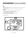
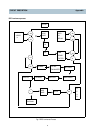
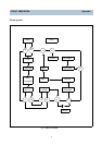
This audio circuit uses a LA71598SM Super A/V 1 chip IC made by SANYO.
The major features of this IC is that REC/EE mode, PB/EE mode, SP/LP mode and audio input
selection are controlled by parallel.
21 pin ( 1~9 pin, 75~80 pin, and 95~100 pin ) are related to Audio circuit.
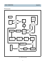
2 Audio IC : name and operation of pins
A. Features
Including PB Amp, Line Amp, REC Amp, ALC circuit, EQ switch and Auto REC bias circuit.
It is equipped with EQ switch operates in SP/LP mode respectively.
ALC level is fixed on 4dBm by values.
B. Function
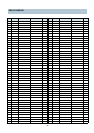
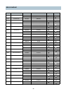
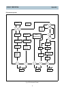
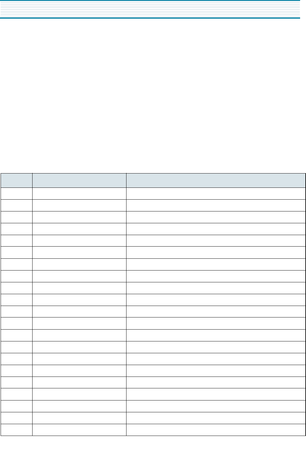
Pin No. Name Function
1 EQ-OUT Playback Amp output
2 EQ-SW2 Capacitor switch for head resonance: in SP or LP, SW ON
3 EQ-NFB Negative feedback of PB Amp
4 EQ-IN Input impedance : 120Kohm
5 EQ-SW1 Playback equalizer switch : in SLP mode, SW ON
6 AUTO-BIAS IN 70KHz signal input for auto-bias
7 AUDIO REC OUT Recording Amp out
8 REC-NFB-SP(GND) GND
9 REC-NFB-LP(GND) GND
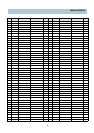
75 AUDIO VCC(5V) Vcc ( 5V )
76 AUDIO-IN Audio in
77 ALC-DET Port for ALC Filter
78 AUDIO-IN2 Audio in
79 VREF Vref filter
80 AUDIO-IN3 Audio in
95 AUDIO-GND GND
96 AUDIO-LINE-OUT Line Amp output
97 ALC-IN ALC detect
98 AUDIO-REC-IN Input to REC Amp
99 AUTO-BIAS-OUT DC control voltage for auto-bias
100 AUDIO-PB-IN Line Amp input of PB Amp out
Appendix