


86
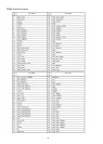
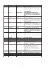
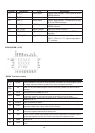
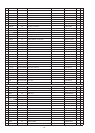
EX3AV (HDMI : IC16)
EX3AV
Terminal Functions
Location Mnemonic Type Description
138 RXB_1+ HDMI Input Digital input channel 1 true of port B in the
HDMI interface.
139 TVDD Power Receiver terminator supply voltage (3.3 V)
140 RXB_2- HDMI Input Digital input channel 2 complement of port
B in the HDMI interface.
141 RXB_2+ HDMI Input Digital input channel 2 true of port B in the
HDMI interface.
142 HP_CTRLC Digital Output Hot Plug Detect for port C.
143 5V_DETC Digital Input 5 V detect pin for port C in the HDMI
interface.
144 DDCC_SDA Digital I/O HDCP slave serial clock port C.
DDCC_SDA is a 3.3 V input/output that is
5 V tolerant.
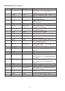
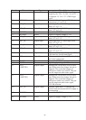
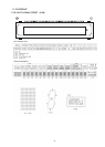
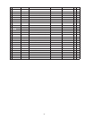
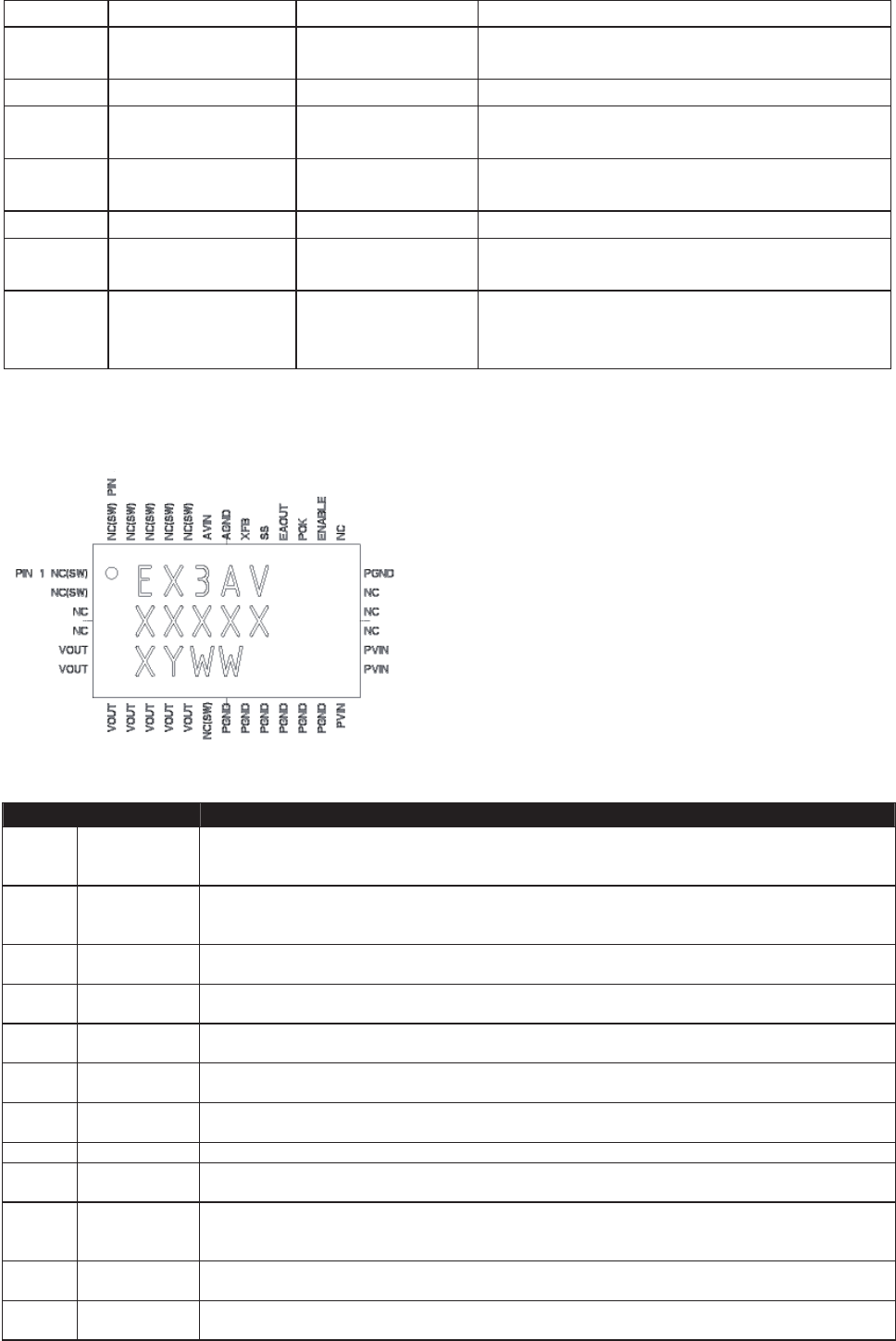
PIN NAME FUNCTION
1-2, 12,
26, 34-
38
NC(SW)
NO CONNECT – These pins are internally connected to the common switching node of the
internal MOSFETs. They are not to be electrically connected to any external signal, ground,
or voltage. Failure to follow this guideline may result in damage to the device.
3-4,
22-25
NC
NO CONNECT – These pins may be internally connected. Do not connect them to each
other or to any other electrical signal. Failure to follow this guideline may result in device
damage.
5-11 VOUT
Regulated converter output. Connect these pins to the load, and place output capacitor
from these pins and PGND pins 13-15
13-18 PGND
Input/Output power ground. Connect these pins to the ground electrode of the Input and
output filter capacitors. See VOUT and PVIN pin descriptions for more details.
19-21 PVIN
Input power supply. Connect to input power supply. Decouple with input capacitor to
PGND pins 16-18.
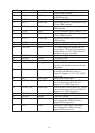
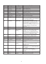
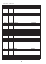
27 ENABLE
Input Enable. Applying logic high enables the output and initiates a soft-start. Applying a
logic low disables the output.
28 POK
Power OK is an open drain transistor for power system state indication. POK will be logic
high when VOUT is with -10% to +20% of VOUT nominal.
29 EAOUT Optional Error Amplifier output. Allows for customization of the control loop response.
30 SS
Soft-Start node. The soft-start capacitor is connected between this pin and AGND. The
value of this capacitor determines the startup time.
31 XFB
External Feedback Input. The feedback loop is closed through this pin. A voltage divider at
VOUT is used to set the output voltage. The mid point of the divider is connected to XFB. A
phase lead capacitor from this pin to VOUT is also required to stabilize the loop.
32 AGND
Analog Ground. This is the Ground return for the controller. Needs to be connected to a
quiet ground.
33 AVIN
Input power supply for the controller. Needs to be connected to input voltage at a quiet
point.