


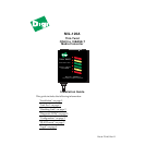

Install Guide
Model: MIL-120A 2
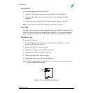
Installation
Do the following to install the MIL-120A:
1. Attach a UTP cable from the network to the MIL-120A's RJ-45 port
2. Attach a T-type BNC connector from the network cabling to the BNC
connector
3. Connect the power adapter's cord from the power source to the unit
Note:
Use shielded twisted pair (CAT 5) cabling for CISPR 22 B installation.
Link Test
The MIL-120A provides a
Link
test function, which is a 10BASE-T standard. The
MIL-120A ships with the
Link
function test “enabled”—only pin one jumpered
with a jumper block. This allows the LEDs to illuminate when there are links.
Disabling Link
To disable the
Link
test:
1. Use a Phillips-head screwdriver to remove the four Phillips-type screws
located on the sides of the unit
2. Remove the BNC nut and its washer
3. Slide the housing off, over the BNC connector
4. Locate the two-pin
Link
jumper (Figure 1)
5. Place the jumper block onto both pins
6. Reassemble the unit (reverse steps 1 through 3)
Note:
The MIL-120A operates in a “StarLAN-10” environment when
Link
is disabled. Only the
Power
and
Link
LEDs Illuminate.
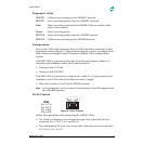
Figure 1.Link and DIP Switch Locations
Link Test
Enabled
1 2
DIP Switch
LINK