


Install Guide
Model: MIL-120A 3
Diagnostic LEDs
COL/TP:
Collisions are occurring on the 10BASE-T network
RCV/TP
Unit is receiving packets from the 10BASE-T network
Link:
There is an active connection to a10BASE-T hub (or another node)
when
Link
is enabled
Power:
Unit is receiving power
RCV/CX
Unit is receiving packets from the 10BASE2 network
COL/CX:
Collisions are occurring on the 10BASE2 network
Configuration
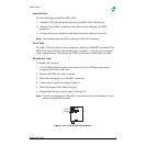
Next to the COAX cable connector, there is a DIP switch that control the 50 ohm
termination resistor (Figure 1). These switches support a variety of configurations.
Both switches are shipped in the UP position (default). Other configurations
include:
If the MIL-120A is connected to the end of a multi-node segment without a T-
connector and terminator, enable the 50 ohm resistor by:
• Placing switch 1: UP and
• Placing switch 2: DOWN
If the MIL-120A is connected to a single-node “without” a T-type connector and
terminator on a COAX cable of less than one meter’s length:
• Place both switches (1 and 2) in the DOWN position
Note:
For this configuration, you do not need a 50 ohm terminator on the COAX segment of the
MIL-120A's BNC connector.
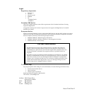
RJ-45 Pinouts
Figure 2. RJ-45 Pinouts
Follow these guidelines when connecting the 10BASE-T Port:
• For a Hub or a Repeater, use a straight-through cable (where the pins are
connected 1 to 1, 2 to 2, 3 to 3, and 6 to 6)
• For a Workstation/PC port, use a swap cable (where the pins are connected 1
to 3, 2 to 6, 3 to 1, 6 to 2)
1
2
3
4
5
6
8
7
MDI
Pin 1=TX+
Pin 2=TX-
Pin 3=RX+
Pin 6=RX-