


20 21
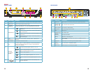
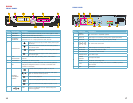
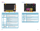
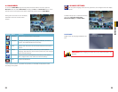
Item #
Connector Description
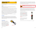
1 Power Switch Power On/Off
2 FAN Cooling fan exhaust port. This should not be blocked.
3
DC 12V Power Connection
4 VIDEO IN BNC connectors for up to four cameras
5 RJ45 For connecting Ethernet cable
6
USB port for the mouse
7
AUDIO
PORTS
BNC ports. Input for a single audio channel. Output to an
external speaker. Connecting an external speaker will not affect
the DVR’s internal speaker.
8 RS485 RS485 for connecting PTZ camera
9 VIDEO OUT Video output for connecting to a TV (BNC)
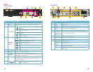
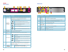
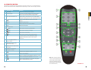
Item # Name/ Symbol Description
1 SCREEN 7” LCD screen
2 LCD ON/OFF Turns the screen on or off. The DVR will still operate.
3
STANDBY/
DISPLAY
MODE
Pressing and holding will bring up the menu to put the DVR to
sleep or turn it off.
Pressing and releasing the button will cycle through the individual
channels or display all four channels simultaneously.
4 MENU/EXIT Press to open/close the main menu.
5
NAVIGATION
▲
Press to move cursor up; in PTZ mode, press to pan
camera up.
▼
Press to move cursor down; in PTZ mode, press to
pan camera down.
◄
Press to move cursor left; in PTZ mode, press to pan
camera left.
►
Press to move cursor right; in PTZ mode, press to
pan camera right.
6
OK
In menus, press to confirm selections; in PTZ mode, press to
change the navigation buttons to control a connected PTZ
camera (not included)
7 IR SENSOR IR Receiver for remote control.
8 LED
INDICATORS
Shows power, recording status, motion detection (Alarm), hard
drive and network connection status
9
USB The upper port is to connect a USB flash drive for
data backup and firmware upgrades.
The lower port is to connect a USB mouse.
SPEAKER
QS4474
FRONT PANEL
REAR PANEL
HDD NETALMREC
Standby
POWER
LCD
ON/OFF
MENU
EXIT
OK
QS4474
1
2
3
7 9
8
4
6
5
RS485-A
RS485-B
GND
DC +12V
IN
RJ45
1 2 3 4
IN OUT
VIDEO IN AUDIO
ON OFF
-
+
VIDEO OUT
1 2
3 5 7 94 6 8