


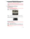

Digital Video Recorder User Manual
8
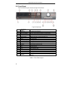
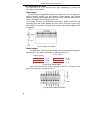
2.3.2 Installing Sensor Alarm
The DVR has 4, 8, or 16 channel alarm input (depending on model) and
four-channel alarm output.
Alarm Input:
The alarm input is triggered by electric level (High: 5V, Low: 0V). Users can
connect external sensors, like gas detector, smoke detector and infrared
detector. Once the DVR detects that the electric level meets the setting user’s
make, it will trigger DVR recording or alarm out.
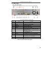
For example, a sensor is connected to alarm input1. Cable A and B will be
connected once the sensor detects an event. Users set Device type as NC
(Normal Close). It will input +5V (high level) to input1 when events happen. DVR
is triggered.
Fig 2.7 Sensor Connection
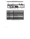
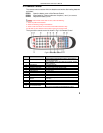
Alarm output:
The DVR has 4-channel relay alarm output, which just gives on/off signal to
external alarm. The status of these pin are illustrated as Fig. 2.7.
N O
COM
N C
N O
COM
N C
Before alarm
After alarm
Fig 2.8 Relay Output Status
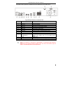
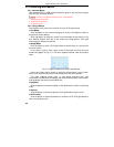
Users need connect their alarm according to the NO or NC type of the
alarm. One connection example as Fig 2.8
Fig 2.9 Alarm Output Connection